Complete Guide to Installing TW VISION Modular LED Panels for Video Walls
Installing a modular LED Video Wall with TW VISION panels requires careful planning, precise execution, and attention to long-term maintenance. This guide walks you through every step — from site survey and structural requirements to power distribution, data cabling, calibration, and maintenance — to ensure a reliable, high-quality video wall that performs consistently in commercial and creative environments.
Overview of TW VISION Modular LED Panels
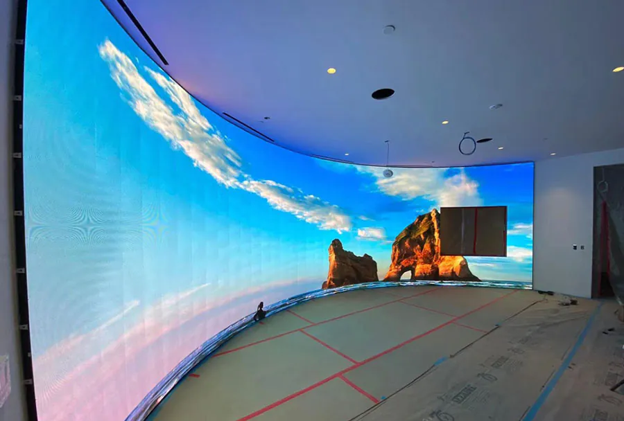
TW VISION modular LED panels are designed for scalable, high-resolution video walls used in control rooms, retail, broadcast, corporate lobbies, and event production. Their modular nature allows for flexible sizes and aspect ratios, but that flexibility also demands strict adherence to installation standards: precise alignment, secure mounting, correct power and signal routing, and professional calibration. This guide assumes indoor commercial installation, but includes notes for semi-outdoor solutions where applicable.
Planning & Site Survey
A thorough site survey is the first step:
– Measure the installation area and confirm wall flatness and load-bearing capacity. LED video walls are heavy when panels are assembled and require a strong backing or freestanding frame.
– Determine ambient light levels and viewing distances to select the appropriate pixel pitch. Closer viewing requires finer pitch.
– Verify HVAC and ventilation — LED panels generate heat and need sufficient airflow.
– Plan route for power, data, and grounding. Identify service access points for maintenance and spare panel storage.
– Confirm local electrical code and permitting requirements, and plan for smoke detectors, fire suppression, and emergency egress considerations where necessary.
Tools & Materials Checklist
Prepare these before starting:
– Mechanical: levels, plumb line, laser level, torque wrench, drill/driver, stud finder, and scaffold or lift.
– Electrical: multimeter, voltage tester, cable testers, PPE (gloves, safety glasses), surge protectors.
– Mounting hardware: rails, brackets, anchors, M6/M8 metric bolts (as specified by TW VISION manual), shims, and grounding straps.
– Cabling: power cables (rated for load + local code), CAT6/CAT6A or fiber for data (as specified), redundant signal paths if required.
– Calibration tools: colorimeter, signal generator, laptop with calibration software, spare power and data modules.
Preparing the Mounting Structure
A stable, perfectly flat mounting structure is critical for seamless seams between panels.
– Confirm structural capacity: calculate total weight of assembled panels plus rails and accessories. Ensure the wall or frame can support at least 1.5× the static load for safety.
– Use a true flat backing (steel or aluminum frame recommended for precision). Wood or block walls often require a metal subframe.
– Install leveling rails or a hanging rail system. Laser level and shims should be used to guarantee flatness within tolerance specified by the panel manufacturer (commonly within 0.5–1.0 mm across the display surface).
– Define service access panels and an access walkway if the installation is large or ceiling-mounted.
Mounting Methods
– Wall-mounted rails: good for permanent installations; allow for micrometric adjustments.
– Rack-mounted frames: suitable for modular reconfiguration and ease of service.
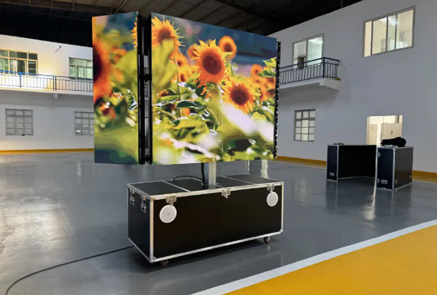
– Ground-supported frames: for freestanding installations or temporary events, ensure base is weighted and secured.
Panel Installation Step-by-Step
1. Unpack and inspect: check each TW VISION panel for physical damage and verify serial numbers against packing lists.
2. Pre-fit one corner: install the first panel at top-left (or bottom-left depending on design), aligning carefully to the leveling rail. Fasten according to torque specs.
3. Progressive alignment: install adjacent panels sequentially, checking seam alignment, squareness, and front surface continuity with a straightedge or laser alignment tool.
4. Mechanical locking: engage panel locking mechanisms and secondary safety bolts. Verify that panel faces are flush and that gaps conform to manufacturer tolerance.
5. Repeat until the full matrix is assembled. For large walls, use a team to avoid stress on mounts and maintain consistency.
6. Label panels and cables to match a wiring diagram for future maintenance.
Analysis Table: TW VISION Modular Panel Comparison
| Model | Pixel Pitch | Typical Brightness (nits) | Weight per Panel | Recommended Use |
|---|---|---|---|---|
| TW VISION Indoor A | 1.9 mm | 600–1000 (typical) | 8–10 kg | Control rooms, Broadcast, Corporate lobbies |
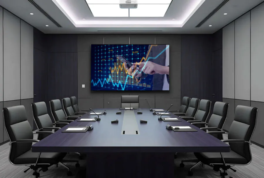
| TW VISION Indoor B | 2.6 mm | 600–1200 (typical) | 9–11 kg | Retail, Conference rooms, Digital signage |
| TW VISION Indoor/Outdoor C | 3.9 mm | 1500–3000 (typical) | 10–12 kg | Semi-outdoor fa?ades, Events, Large venues |
| TW VISION Outdoor D | 4.8 mm | 3000–7000 (typical) | 12–15 kg | Outdoor billboards, Stadium screens |
Note: The values above are typical ranges for modular LED panels and should be verified with TW VISION’s datasheets for exact model specifications and tolerances.
Electrical and Data Connectivity
Proper power and signal distribution is essential for reliability and image quality.
Power Distribution
– Calculate total current draw: refer to panel power specs and multiply by the number of panels, then add headroom (20–30%) to accommodate peak usage.
– Use dedicated lighting-grade or AV-grade circuits, distributing loads across multiple breakers to minimize single-point failures.
– Implement redundant power feeds where uptime is critical. Use automatic transfer switches or dual PSUs in controllers if supported.
– Grounding: establish a single-point earth ground for the entire video wall system to avoid ground loops and protect sensitive electronics.
– Surge protection and UPS: include surge protection at the service entrance and a UPS for control and signal equipment. For very large walls, consider UPS for power zones to allow graceful shutdown during power loss.
Signal & Cabling
– Data cabling options: copper CAT6/CAT6A for short runs, fiber optic for long distances or high-density deployments. Follow TW VISION’s recommended signal protocols (e.g., proprietary or standard video-over-ethernet protocols).
– Clocking and synchronization: ensure panels receive proper timing signals; some panels require a master controller or sync cable daisy-chain.
– Cable management: label both ends, use cable trays, and maintain bend-radius for fiber. Consider redundant routes for mission-critical walls.
– Controller placement: locate the video processor and media server in an accessible, cooled equipment rack near the video wall, with clean cable runs to the panels.
Calibration, Testing, and Tuning
A newly installed wall will need color calibration and functional testing.
Color Calibration & Uniformity
– Warm-up: allow the panels to reach stable operating temperature (typically 30 minutes to an hour).
– Use a professional calibration tool (colorimeter/spectroradiometer) and software to balance gamma, white point, and grayscale across the entire wall.
– Adjust brightness and contrast to meet the ambient light conditions and desired image fidelity.
– Run uniformity tests to check for dead pixels, color shifts, or brightness variation. Replace or adjust panels that fall outside acceptable thresholds.
Functional Tests
– Run multi-pattern test sequences: grid, grayscale ramp, color bars, and motion tests.
– Verify synchronization, latency (if interactive), and input source switching.
– Test redundancy: switch power and signal paths to ensure failover behaves as planned.
Maintenance & Troubleshooting
Regular maintenance will extend the life and performance of your TW VISION installation.
– Cleaning: use soft, lint-free cloths and approved cleaning solutions. Do not spray liquids directly onto panels.
– Inspection schedule: monthly visual inspections for loose mounts, cable strain, or heat accumulation; quarterly electronic diagnostics for pixel health and brightness drift.
– Spare parts: keep spare modules, power supplies, signal cards, and standard fasteners on hand for prompt replacement.
– Common issues: dead pixels (replace LED module), uneven brightness (recalibration or power rail check), synchronization artifacts (check signal chains and cable integrity), and overheating (improve ventilation or adjust duty cycles).
– Firmware and software: apply updates for controllers and processors only after vetting in a test environment. Maintain revision control and backups of configuration files.
Safety and Best Practices
– Comply with local electrical and building codes and use licensed electricians for power connection and grounding.
– Use fall protection and safe lifting practices during installation. Panels can be heavy and fragile.
– Keep documentation: as-built wiring diagrams, panel serial numbers, calibration reports, and maintenance logs should be stored both onsite and in the cloud.
– Training: provide operator and maintenance staff with basic training on safe operation, routine checks, and emergency shutdown procedures.
– Warranty and support: register the installation with TW VISION, document any deviations from standard procedures, and establish a service contract for periodic preventive maintenance.
Final thoughts: A professional installation of TW VISION modular LED panels is a multidisciplinary project requiring mechanical precision, electrical discipline, and careful calibration. Investing time in planning, using correct mechanical supports, implementing robust power and signal infrastructures, and following structured maintenance procedures will yield a visually seamless, reliable video wall that delivers value for years. If you’re unsure about structural or electrical aspects, engage certified integrators or TW VISION’s technical support early in the process to minimize rework and ensure compliance with manufacturer recommendations.