TW VISION Bendable Screen Complete Guide for Flexible Display Solutions
flexible displays are no longer a conceptual novelty. They are an enabling platform for new product forms, user experiences, and industrial applications. TW VISION’s bendable screen line positions itself as a practical, scalable solution for manufacturers seeking to integrate flexible display technology into consumer electronics, automotive interfaces, wearables, and commercial signage. This guide explains the core technologies, performance characteristics, design and integration best practices, manufacturing considerations, reliability testing, and future directions for TW VISION bendable screens—helping engineers, product managers, and procurement teams make informed decisions.
What Is a TW VISION Bendable Screen?
TW VISION bendable screens are flexible display modules engineered to tolerate curvature and bending while maintaining optical performance and touch responsiveness. These modules typically employ OLED or flexible LCD backplanes, low-temperature polycrystalline silicon (LTPS) or oxide TFTs, thin-film encapsulation, and flexible printed circuit interconnects to achieve a thin, lightweight, and mechanically resilient product.
Key Differentiators
– High bend radius tolerance: optimized mechanical stack-up to survive cyclic bending.
– High brightness and contrast: OLED options for true blacks and vivid colors; flexible LCD for high ambient performance.
– Integration-friendly form factors: custom sizes, aspect ratios, and connector placements to fit product designs.
– Industrial-grade testing and validation: thermal, humidity, and mechanical life-cycle testing per customer requirements.
Core Technologies Behind Bendable Displays
Flexible OLED vs. Flexible LCD
– Flexible OLED: Emissive technology that excels in color accuracy, contrast, and thinness. It can be fabricated on plastic substrates (PI) or thin glass, enabling tight bending radii.
– Flexible LCD: Uses a reflective or transflective approach with a flexible backplane and specialized polarizers. It often provides higher peak brightness in very bright environments but requires a backlight layer, increasing thickness.
Thin-Film Transistors (TFT) and Backplanes
– LTPS TFTs: Provide high mobility for high-resolution displays and efficient drive currents—favored in high-performance wearable and mobile applications.
– Oxide TFTs (IGZO, a-IGZO): Offer low leakage and good uniformity, suitable for larger-area displays and lower-power applications.
Encapsulation and Barrier Technologies
Moisture and oxygen are OLED killers. TW VISION implements thin-film encapsulation (TFE) or hybrid glass/plastic stacks to provide the necessary barrier performance while maintaining flexibility. Multi-layer inorganic/organic stacks balance barrier performance and flexibility.
Flexible Interconnects and Touch
Flex PCBs, anisotropic conductive films (ACF), and printed conductive traces are used for signal routing. Projected capacitive touch can be integrated using flexible touch sensors laminated onto the display.
Mechanical and Optical Specifications
Key specs engineers should review when evaluating TW VISION modules include bend radius (static and dynamic), bend cycles (lifetime), module thickness, areal weight, resolution (ppi), brightness (nits), contrast ratio, color gamut (NTSC or DCI-P3), and touch integration.
Typical Performance Ranges
– Bend radius: as low as 3–8 mm for small wearable panels; 10–30 mm for larger panels.
– Bending cycles: 100k–1M cycles depending on design and stress profile.
– Panel thickness: 0.2–1.2 mm depending on encapsulation and backlight for LCD.
– Brightness: 300–1000 nits for OLED; up to 1500+ nits for transflective/flexible LCD with strong backlight.
– Resolution: 300–800+ ppi for small devices; lower ppi acceptable for signage.
Applications and Use Cases
Consumer Electronics
Foldable phones and tablets, rollable displays, next-gen laptops, and wearable devices (smartwatches, fitness bands) leverage TW VISION for compact form factors and novel UX.
Automotive and HMI
Flexible displays enable curved instrument clusters, wraparound center consoles, and dynamic ambient lighting panels. Automotive applications require extended temperature ranges, vibration resistance, and long-term reliability.
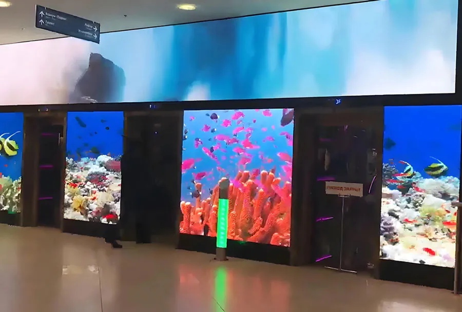
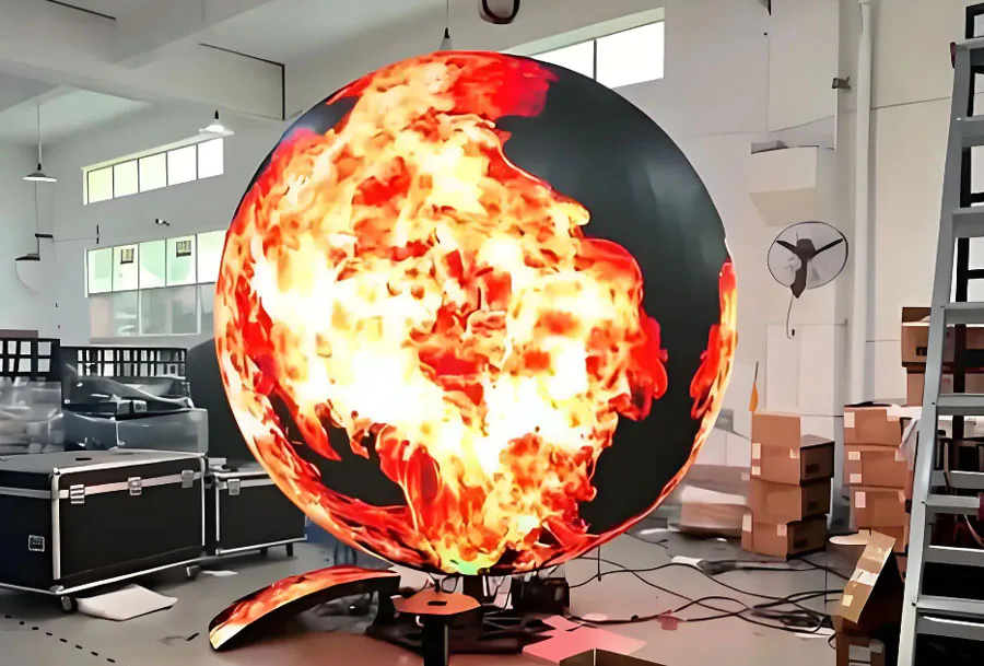
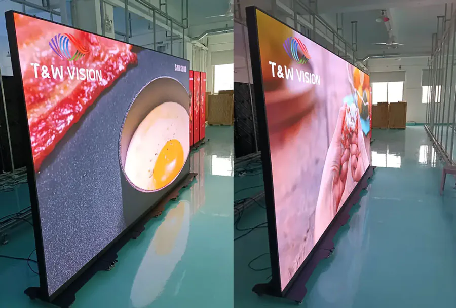
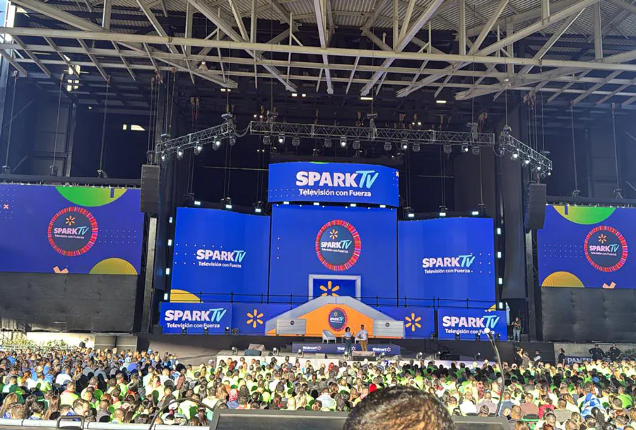
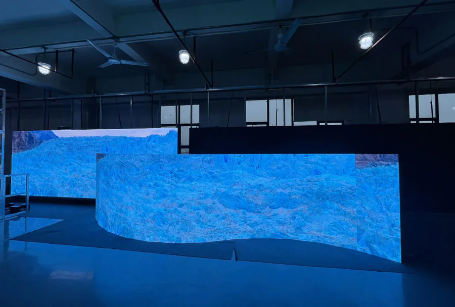
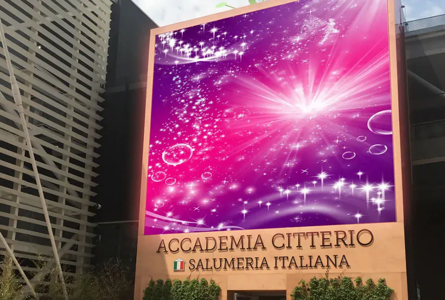
Commercial Signage and Retail
Rollable banners, curved shopfront displays, and immersive kiosks use bendable screens to create engaging visual experiences with reduced installation complexity.
Industrial and Medical
Curved diagnostic displays, wearable medical monitors, and robust field equipment can benefit from flexible screens that conform to ergonomic constraints or protective housings.
Design and Integration Best Practices
Mechanical Integration
– Define allowable bend regions early: keep rigid components (connectors, chips) out of high-flex zones.
– Use strain-relief patterns in flex cables and follow recommended minimum radii where mounting or routing occurs.
– Consider neutral plane placement: place the display’s active layer near the neutral axis to minimize tensile/compressive strain during bending.
Thermal and Power Management
OLED power scales with brightness and content. Implement adaptive brightness, local dimming (if supported), and thermal conduction paths to avoid hotspots that speed degradation.
Optical and Touch Considerations
– Anti-reflective coatings and high-brightness options improve outdoor readability.
– Calibrate touch algorithms for the changing curvature profiles—dynamic calibration may be needed for foldable devices.
Reliability, Testing, and Qualification
Rigorous testing is essential for product success. TW VISION modules are typically tested for:
– Bending cycles (dynamic fatigue) and static bend hold.
– Thermal cycling across the operating temperature range (-40°C to +85°C for industrial/automotive variants).
– Humidity and salt-fog testing for coastal or harsh environments.
– Vibration and shock for automotive and field equipment.
Testing must be performed in the intended device context (with housing, adhesives, and EMI shields applied) because integration can significantly change stress profiles.
Manufacturing and Supply Chain Considerations
Flexible displays introduce supply-chain nuances:
– Lead times: custom sizes and low-volume variants can increase lead times; TW VISION can support scalable production but early volume commitments reduce risks.
– BOM complexity: flexible modules often require specialized adhesives, encapsulation films, and connectors—source redundancy helps mitigate shortages.
– DFM (Design for Manufacturing): collaborate closely with TW VISION’s engineering team during early design to align aperture sizes, connector locations, and curvature specs.
Cost Drivers and Trade-offs
– OLED vs. LCD: OLED typically costs more but offers superior contrast and thinner stacks; flexible LCDs can be competitive for high-brightness needs.
– Barrier performance: higher moisture barriers increase cost but extend lifetime.
– Custom shapes and small orders increase unit cost due to tooling and panel utilization.
Comparative Analysis Table
| Feature | Technical Parameter | Typical Range / Value | Impact on Application | Design Consideration |
|---|---|---|---|---|
| Flexibility | Bend radius (static/dynamic) | 3–30 mm | Determines allowable device form factors (folds, rolls) | Avoid rigid components in high-flex regions; set neutral plane |
| Lifetime | Bend cycles to failure | 100k–1M cycles | Affects product longevity and warranty strategy | Specify target cycles; test in assembled configuration |
| Optical Performance | Brightness & Contrast (nits / ratio) | 300–1500 nits; 1,000:1–>100,000:1 (OLED) | Readability in ambient light; image quality | Choose OLED vs LCD based on ambient environment needs |
| Barrier | WVTR (Water Vapor Transmission Rate) | 10^-4–10^-6 g/m^2/day | Directly impacts OLED lifetime | Select TFE level per lifetime targets; consider hybrid seals |
| Interconnect | Connector type & flex PCB stacking | FPC/FFC with ACF or board-to-board | Affects assembly complexity and signal integrity | Plan cable routing, strain relief, and EMC shielding |
Case Studies and Example Implementations
Wearable Health Monitor
A wearable company integrated a 1.6″ TW VISION bendable OLED with a 5 mm bend radius to create a contoured wrist display. Design choices:
– LTPS backplane for high resolution.
– Thin-film encapsulation with secondary seal.
– Neutral-plane alignment to maximize bend-cycle life.
Result: reliable 500k cycle performance and excellent outdoor readability due to 600 nits peak brightness.
Automotive Curved Cluster
An OEM used a 12.3″ TW VISION flexible LCD for a wraparound dash display. Requirements included extended temperature operation and vibration tolerance:
– Oxide TFT backplane for uniformity.
– High-brightness backlight with polarizer treatments for sunlight readability.
– Specialized adhesives and mechanical mounts to avoid stress concentrations.
Result: compliant with automotive thermal and mechanical specs; integration with HUD and instrument sensors.
Challenges and Mitigation Strategies
– Delamination and cracking: Use compliant adhesives, correct cure profiles, and ensure clean surfaces during lamination.
– OLED aging and burn-in: Implement pixel-shift algorithms, content-aware dimming, and lifetime management (reduce peak brightness).
– Connector failures: Employ redundant traces where possible and use strain-relief designs.
– Environmental exposure: Select appropriate barrier levels and implement secondary seals for high-humidity environments.
Regulatory and Compliance Considerations
Automotive, medical, and some industrial applications demand specific certifications (ISO 26262 for functional safety contexts, IEC 60601 for medical devices, automotive GMW/TS standards). Work with TW VISION to document materials, outgassing, and test evidence required for regulatory submissions.
Future Trends and Roadmap
– Thinner stacks and improved barriers: Advances in TFE and substrate chemistry will reduce thickness and increase OLED lifetime.
– Higher resolution flexible panels: LTPS and oxide TFT improvements will push ppi up while maintaining power efficiency.
– Integration of haptics and micro-LEDs: Haptic layers laminated onto flexible displays and micro-LED arrays may enable new tactile-plus-visual experiences.
– Scalable manufacturing: Roll-to-roll processing and larger flexible glass substrates will lower costs and enable higher-volume markets.
Selecting a TW VISION Module: Checklist
– Define mechanical profile: static vs dynamic bending, bend radius, and fold locations.
– Specify optical targets: brightness, color gamut, and contrast.
– Establish lifetime requirements: bend cycles, operating hours, warranty period.
– Verify environmental requirements: operating temperature, humidity, ingress protection.
– Integration constraints: connector location, module thickness, touch integration.
– Supply chain demands: lead time, volumes, long-term support.
Aligning Product Goals with Flexible Display Capabilities
TW VISION bendable screens provide a practical pathway to implement flexible display features across multiple industries. Successful products result from early cross-functional collaboration—mechanical, electrical, optical, and manufacturing teams must define constraints and iterate with suppliers. By understanding the technical trade-offs (OLED vs. LCD, barrier performance, bend mechanics) and by following rigorous testing and DFM principles, teams can bring durable, high-impact flexible display products to market. As materials and production technologies evolve, bendable screens will continue to unlock innovative user experiences and new product form factors—making now an optimal time to evaluate and integrate TW VISION’s flexible display solutions.