From Brand Concept to Factory-Ready Design: How to Freeze Custom LED Screen Geometry

From Brand Concept to Factory-Ready Design: How to Freeze Custom LED Screen Geometry starts with a practical question: can you build, assemble, and service your approved shape without changing its visual intent?
Table of Contents
- 1. Translate Brand Intent Into Measurable Geometry
- Establish the controlling references
- 2. Fit the Shape to the Actual LED Module System
- Check physical dimensions and pixel dimensions separately
- 3. Resolve Structure, Services, and Installation Interfaces
- Check the space needed to operate and maintain the screen
- 4. Define Tolerances and Prove the Critical Details
- Separate component tolerances from assembly acceptance
- 5. Release a Controlled Manufacturing Package
- Make the release internally consistent
- Who should own the editable design files?
- What happens if the selected LED module is discontinued?
- How should you protect confidential brand geometry when requesting quotes?
- When can fabrication start before the complete design is approved?
- How do transport restrictions affect an already approved screen?
- Put the Geometry Freeze Into Practice
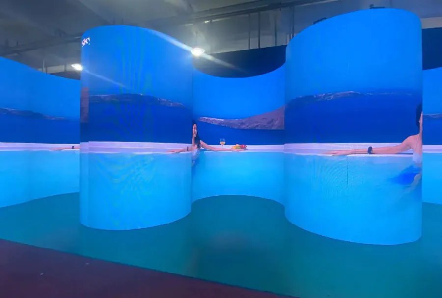
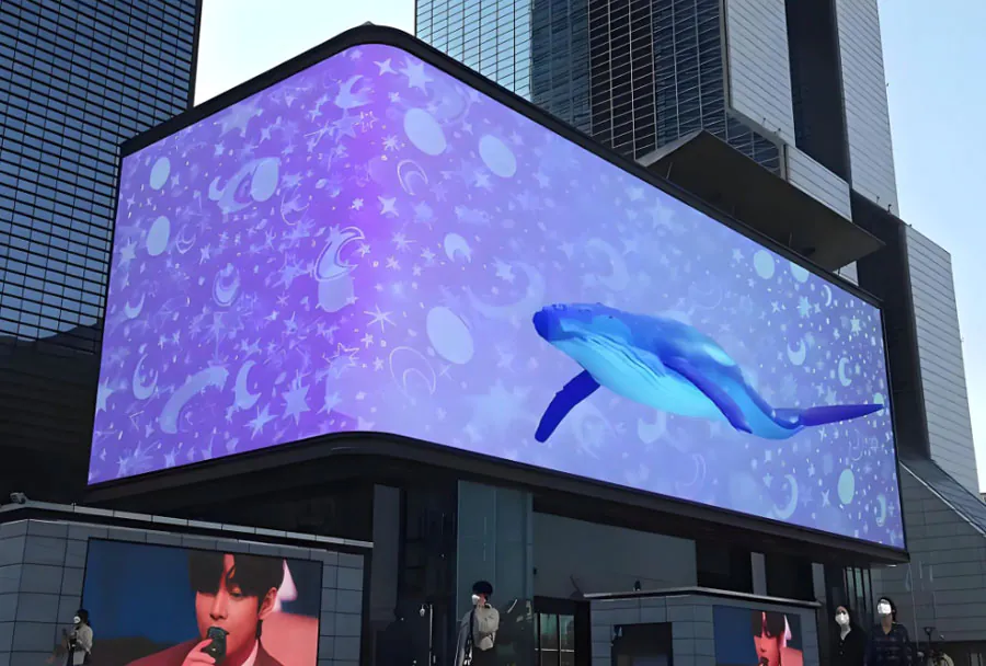
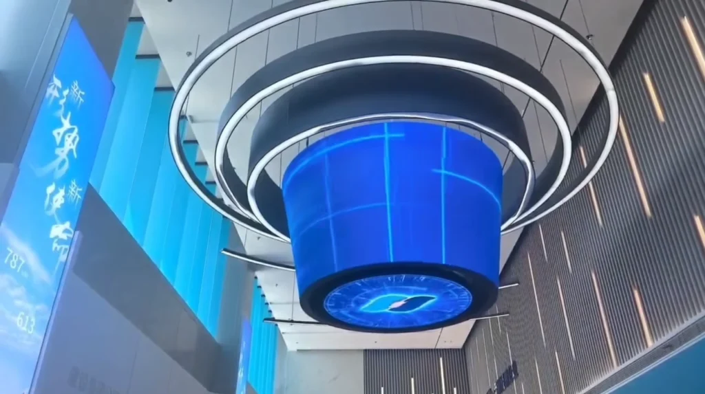
A surprising fact is that a smooth curve in a rendering can become a series of flat faces when built from rigid LED cabinets. The same silhouette may require curved modules, faceted cabinets, or a different support structure, depending on the product you select.
That gap between appearance and construction creates difficult decisions. Your brand team approves the outline, while engineering still needs to resolve module boundaries, mounting points, cable routes, and access.
A reliable geometry freeze turns those decisions into a controlled manufacturing baseline. You need a shared coordinate system, a verified module layout, measurable acceptance criteria, and a release package that connects the visible surface to the structure behind it. These steps help you preserve the design while giving the factory clear instructions.
1. Translate Brand Intent Into Measurable Geometry
A useful geometry brief defines the visible shape, its location, and the features that must survive engineering changes.
Start by separating design intent from manufacturing constraints. Design intent covers the silhouette, proportions, viewing position, and relationship to surrounding architecture; manufacturing constraints cover available modules, mounting interfaces, access, and material behavior.
For From Brand Concept to Factory-Ready Design: How to Freeze Custom LED Screen Geometry, your first deliverable should be an approved reference model with named dimensions.
Establish the controlling references
Record the following information:
– Overall visible width, height, and depth.
– Origin, units, axis directions, and installation orientation.
– Curve definitions, tangent points, and transition boundaries.
– Active display boundary and surrounding trim.
– Building interfaces and verified survey references.
Rhino supports NURBS geometry and is useful for defining complex surfaces. McNeel’s official Rhino features documentation states that the software can create, edit, analyze, and document NURBS curves and surfaces.
That capability helps turn an approved visual shape into inspectable geometry, but it does not establish whether a selected LED product can follow the surface.
Consider a brand ribbon wrapping around a corner: its outer silhouette may be fixed while the concealed rear enclosure remains adjustable. Marking that distinction gives engineers room to solve mounting and access.
Treat From Brand Concept to Factory-Ready Design: How to Freeze Custom LED Screen Geometry as a shared brief that identifies which features require brand approval before modification.
How to apply this: Annotate your reference model with the controlling dimensions and label each feature as fixed, adjustable, or awaiting verification.
2. Fit the Shape to the Actual LED Module System
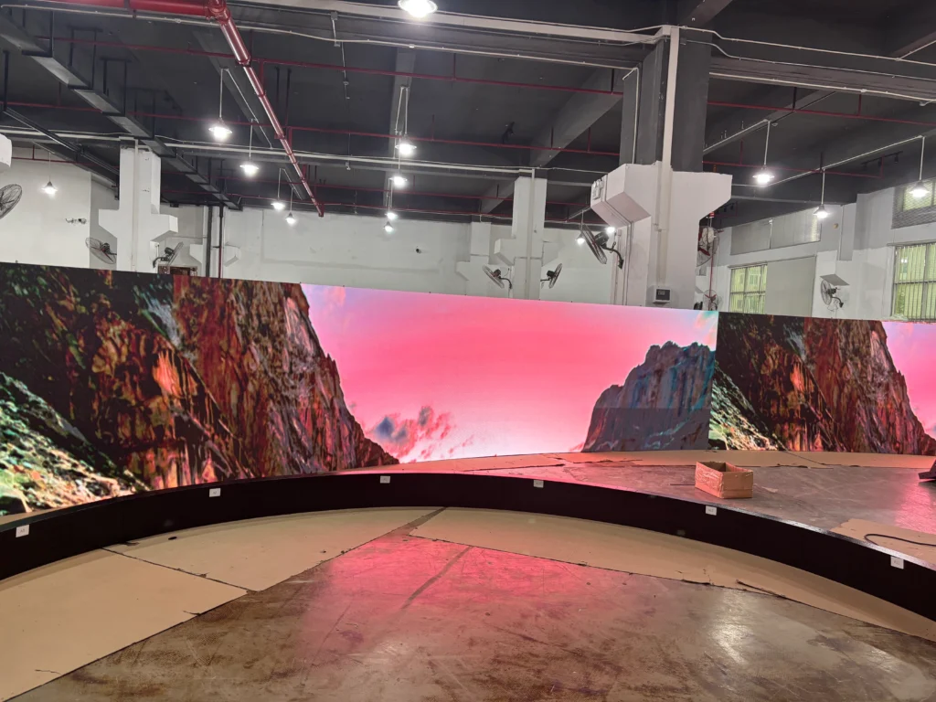
A buildable LED layout fits the approved surface to verified module dimensions, allowable curvature, and edge conditions.
Select a candidate module family before committing to the final outline. Obtain its mechanical drawing, pixel layout, connector positions, mounting details, and any documented bending limits.
In From Brand Concept to Factory-Ready Design: How to Freeze Custom LED Screen Geometry, the module drawing supplies the manufacturing data that a rendering cannot provide.
Check physical dimensions and pixel dimensions separately
For a rectangular array, total pixel width equals the number of modules across multiplied by each module’s horizontal pixel count. Physical width must come from the mechanical layout, including specified joints and edge details.
Do not assume that pixel pitch multiplied by pixel count always gives the finished enclosure dimension. The display lattice, module envelope, and external trim describe different boundaries.
| Geometry choice | Main constraint | Action to take |
|---|---|---|
| Flat array | Module envelope | Check edge dimensions |
| Faceted curve | Cabinet joint angles | Review visible breaks |
| Flexible surface | Documented bend limits | Confirm permitted direction |
| Shaped outline | Available module shapes | Map incomplete edges |
| Wrapped corner | Joint construction | Inspect a sample |
A common scenario is a circular brand mark that cannot align exactly with the selected rectangular modules. You may need a stepped active boundary behind a mask, a revised outline, or purpose-made modules.
Evaluate those options before freezing the surface. From Brand Concept to Factory-Ready Design: How to Freeze Custom LED Screen Geometry depends on approving the real illuminated boundary as well as the outer silhouette.
How to apply this: Overlay the supplier’s module outlines on your approved shape and highlight every boundary that requires masking, custom hardware, or a design decision.
3. Resolve Structure, Services, and Installation Interfaces
Geometry is ready to freeze only when the visible surface and its supporting systems fit within the same verified envelope.
Your coordination model should include the display, cabinets, structural frame, attachment points, power equipment, data connections, ventilation spaces, and service access. Each element can change the required depth or position.
From Brand Concept to Factory-Ready Design: How to Freeze Custom LED Screen Geometry therefore requires input from the installer and structural engineer before release.
Check the space needed to operate and maintain the screen
A useful clearance check compares available space with the complete service envelope: component depth, connector projection, cable bend requirements, removal movement, and installation tolerances. Use the selected equipment’s documentation for those inputs.
SOLIDWORKS provides assembly modeling and interference detection. These functions can reveal overlapping modeled parts, although they cannot verify maintenance access unless you also model the required movement and working space.
For an outdoor enclosure, define the environmental requirement separately from appearance. The International Electrotechnical Commission’s explanation of IP ratings describes protection against intrusion by solids and water; an IP designation does not establish structural capacity or corrosion resistance.
In one case, a front-service module may release correctly but still strike a nearby architectural return during removal. A static clearance check would miss that movement.
Record these interface decisions alongside the display geometry. From Brand Concept to Factory-Ready Design: How to Freeze Custom LED Screen Geometry should include named owners for unresolved building and equipment constraints.
How to apply this: Review a coordinated assembly with the installer and trace the full removal path of the least accessible replaceable component.
4. Define Tolerances and Prove the Critical Details
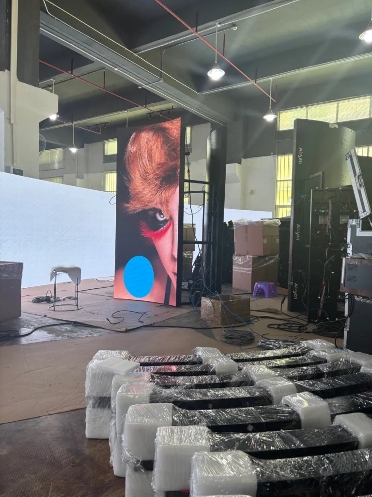
A geometry freeze needs measurable acceptance criteria for both individual parts and the assembled display.
“Match the model” is insufficient because manufacturing, assembly, and site conditions introduce variation. Define which dimensions control appearance, alignment, module fit, and attachment compatibility.
For From Brand Concept to Factory-Ready Design: How to Freeze Custom LED Screen Geometry, tolerances should reflect supplier capability and project requirements rather than copied drawing notes.
Separate component tolerances from assembly acceptance
Identify how each feature will be checked:
– Module seating surfaces against defined datums.
– Adjacent module alignment across a joint.
– Overall outline against the approved reference.
– Mounting positions against the installation interface.
– Curved surfaces against agreed inspection sections.
For a linear chain of dimensions, a worst-case tolerance calculation adds the absolute contributions of the relevant dimensional tolerances. That relationship can expose an assembly that fails to fit even when every individual component meets its drawing.
AutoCAD supports dimensioned drawings that can communicate datums, interfaces, and inspection requirements. Keep those drawings consistent with the released model and document precedence if a discrepancy arises.
Suppose a curved seam is prominent from the main entrance. A representative physical sample can reveal alignment, masking, and viewing effects that a dimensional review alone will not settle.
Make the sample’s acceptance criteria explicit before inspection. From Brand Concept to Factory-Ready Design: How to Freeze Custom LED Screen Geometry works best when approval records identify the tested configuration and any limitations.
How to apply this: Select the interface most likely to cause rework, agree on its measurable acceptance criteria, and verify it through a sample or documented inspection.
5. Release a Controlled Manufacturing Package
A factory-ready release combines approved geometry, manufacturing instructions, inspection criteria, and a clear process for later changes.
Freezing geometry means establishing a baseline that production can trust. It does not mean that every future change is prohibited.
The final stage of From Brand Concept to Factory-Ready Design: How to Freeze Custom LED Screen Geometry is making that baseline unambiguous.
Make the release internally consistent
Your package should contain:
– Approved models with units, origin, orientation, and revision identifiers.
– Manufacturing drawings with datums and critical dimensions.
– Module maps showing orientation, identification, and active boundaries.
– Interface drawings for structure, power, data, and access.
– Inspection requirements and approved sample records.
– A bill of materials linked to the released configuration.
Include the image canvas dimensions and explain their relationship to the physical module map. A display’s total pixel count follows its module arrangement, but that alone does not define controller assignments, content orientation, or masked regions.
Assign approval by responsibility: brand reviewers approve appearance, engineering reviewers approve their technical scope, and production confirms that the package supports manufacture.
A late request to widen a logo cutout illustrates why revision control matters. The adjustment can affect trim, module coverage, structural openings, and the content mask.
Record its consequences before replacing the released baseline. From Brand Concept to Factory-Ready Design: How to Freeze Custom LED Screen Geometry should leave production able to identify which files are current and which approvals they carry.
How to apply this: Issue a release register listing each controlled file, its revision, its approver, and the manufacturing decision it authorizes.
Frequently Asked Questions About From Brand Concept to Factory-Ready Design: How to Freeze Custom LED Screen Geometry
These questions address procurement and delivery situations that can arise after the main geometry decisions are complete.
Who should own the editable design files?
Your contract should specify ownership, permitted use, delivery formats, and access to editable source files. Payment for fabrication does not, by itself, explain what design rights or file access the parties have agreed.
For a project involving proprietary cabinet details, the supplier may provide interface geometry while retaining internal manufacturing files. From Brand Concept to Factory-Ready Design: How to Freeze Custom LED Screen Geometry should therefore include a documented file-delivery agreement before procurement.
What happens if the selected LED module is discontinued?
Treat a replacement module as a proposed configuration change and assess its compatibility before purchase. Matching pixel pitch does not establish matching dimensions, mounting points, connectors, or operating requirements.
If discontinuation occurs during a phased rollout, your original screen may still need compatible spares. From Brand Concept to Factory-Ready Design: How to Freeze Custom LED Screen Geometry should be supported by a procurement plan that records approved substitutions and the evidence required to accept them.
How should you protect confidential brand geometry when requesting quotes?
Share the information needed to price and assess the work under appropriate contractual confidentiality terms. Agree on permitted recipients, file use, storage, and return or deletion requirements with your legal and procurement teams.
An unreleased product launch may require restricted access to the full brand model while bidders receive limited geometry. From Brand Concept to Factory-Ready Design: How to Freeze Custom LED Screen Geometry can proceed through staged disclosure when responsibilities and evaluation requirements are clear.
When can fabrication start before the complete design is approved?
Fabrication can start under a documented partial release when the released scope has stable interfaces and the responsible parties accept the remaining dependencies. Identify exactly which components the authorization covers.
A repeatable support bracket might qualify while a unique corner assembly remains unresolved. From Brand Concept to Factory-Ready Design: How to Freeze Custom LED Screen Geometry requires each partial release to state its boundaries, assumptions, and change exposure so procurement does not interpret it as full approval.
How do transport restrictions affect an already approved screen?
Transport restrictions can require the approved assembly to be divided into smaller shipping units. Check route access, lifting arrangements, packaging envelopes, and delivery openings before accepting that change.
A screen that fits its final wall may still be unable to pass through the building’s loading route. From Brand Concept to Factory-Ready Design: How to Freeze Custom LED Screen Geometry should connect to a delivery plan whenever assembly divisions affect visible joints or site installation.
How to apply this: Add ownership, substitution, confidentiality, partial-release, and transport questions to your procurement review.
Put the Geometry Freeze Into Practice
A successful freeze gives each team a common definition of what will be built and how it will be accepted. From Brand Concept to Factory-Ready Design: How to Freeze Custom LED Screen Geometry becomes manageable when approvals connect appearance to physical evidence.
– Define the silhouette, reference system, and features that require brand approval.
– Validate the module layout against the active image boundary and mechanical envelope.
– Resolve support, access, tolerances, and inspection before releasing dependent parts.
– Publish a consistent package and assess later changes against that baseline.
The useful milestone is a release that your supplier can manufacture, your installer can position, and your reviewers can inspect against agreed criteria.
How to apply this: Bring your current model, module drawings, and installation survey into a joint review, then assign an owner and closure requirement to every unresolved geometry decision.