LED Display Modules: Manufacturing, Quality & Custom Solutions

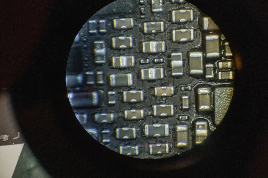
LED Display Modules: Manufacturing is the difference between a video wall that stays uniform for years and one that develops dead pixels within the first season. A single 128 x 64 RGB module contains 8,192 LEDs. With four solder pads per LED, that adds up to about 32,768 solder joints.
Table of Contents
- 1. Treat the PCB and Driver Electronics as the Foundation
- Material Choices That Matter
- Layout Rules That Reduce Field Failures
- 2. Control Solder Paste Deposition Before Reflow
- Stencil and Profile Rules
- Process Control Checks That Prevent Field Failures
- 3. Match Pixel Pitch to the Real Viewing Distance
- Cost and Yield Trade-Offs
- 4. Build Weather Resistance Into the Module Enclosure
- 5. Validate Optical Uniformity Before You Ship
- Why Burn-In Testing Still Matters
- How long does LED display module manufacturing take from order to shipment?
- What is the minimum order quantity for custom LED display modules?
- Can a small electronics shop produce LED display modules in-house?
- Which certifications matter most for LED display module production?
- Why can two batches of the same module look different in brightness?
- Conclusion
At high production volume, even a small defect rate creates a field-reliability problem. Engineering teams often focus on the LEDs and power supplies while missing process steps that determine yield. Five areas separate reliable module builders from the rest: PCB layout, solder paste deposition, pixel pitch selection, environmental protection, and optical validation.
If you specify or produce LED display modules, these are the levers that most affect cost and lifespan.
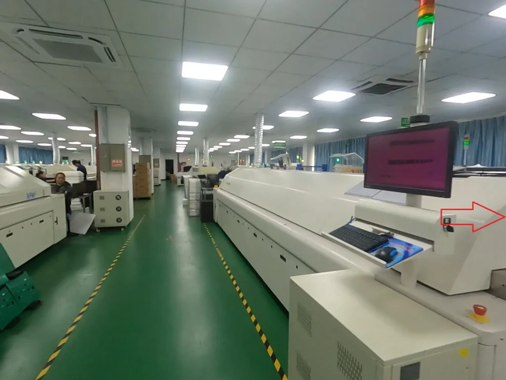
TW VISION‘s factory live video to show you how we do SMT, assembly, module aging and cabinet aging.
1. Treat the PCB and Driver Electronics as the Foundation
Few steps in LED Display Modules: Manufacturing create more hidden risk than the PCB and driver electronics. The board carries high-frequency data, constant-current drive, and thermal load at the same time. A weak layout shows up later as ghosting, uneven brightness, or driver IC failures in the field.
IPC’s J-STD-001 standard defines solder joint acceptability by wetting angle, fillet shape, and void percentage. It remains the baseline for class 2 and class 3 electronics. Many module factories build indoor products to class 2, while rental and outdoor panels often require class 3. You can review the acceptance criteria on the IPC website.
How to apply this: Ask your bare-board supplier and assembly partner which IPC class they actually certify, not just the class shown on the drawing.
Material Choices That Matter
When LED Display Modules: Manufacturing moves below 2 mm pixel pitch, board material choices shift from cost-first to reliability-first. Standard FR-4 works for most indoor modules, but high-Tg laminates hold up better when reflow peak temperatures stay near 250°C.
Use 1 oz copper on signal layers and 2 oz copper on power planes when module current exceeds roughly 5 A per scan line. This prevents voltage drop that dims far-end pixels.
Layout Rules That Reduce Field Failures
Keep the driver IC close to the LED pads. Place thermal vias under the driver’s exposed pad, and separate analog ground from high-current LED return paths. These rules reduce ghosting and improve scan uniformity. Tools such as Altium Designer let you enforce spacing and impedance rules before the board goes to fab.
In high-density LED Display Modules: Manufacturing, design rule checks catch these issues before fabrication.
2. Control Solder Paste Deposition Before Reflow
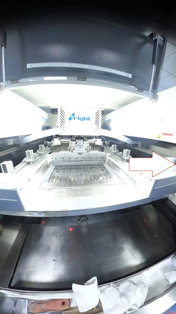
At the center of LED Display Modules: Manufacturing, solder paste printing controls yield more than almost any other process. A misaligned or underfilled paste deposit can pass electrical test and still fail after thermal cycling. This is why high-volume lines put solder paste inspection (SPI) before pick-and-place.
Koh Young SPI systems measure paste volume, height, area, and offset with 3D inspection before components are placed. A typical 0.4 mm pitch QFN driver may require a stencil thickness of 0.1 mm to 0.12 mm, but the correct window depends on pad finish and solder paste type.
How to apply this: Measure paste height right after printing and adjust blade speed or pressure before the first reel of components reaches placement.
Stencil and Profile Rules
Laser-cut stencils work for many modules, but electroformed or nano-coated stencils release paste more consistently on fine-pitch driver pads. For lead-free SAC305 solder, the reflow profile typically peaks in a 240°C to 250°C window. Time above liquidus usually stays between 60 and 90 seconds to avoid voiding and intermetallic growth.
Stable LED Display Modules: Manufacturing treats stencil design as a variable, not a one-time fixture.
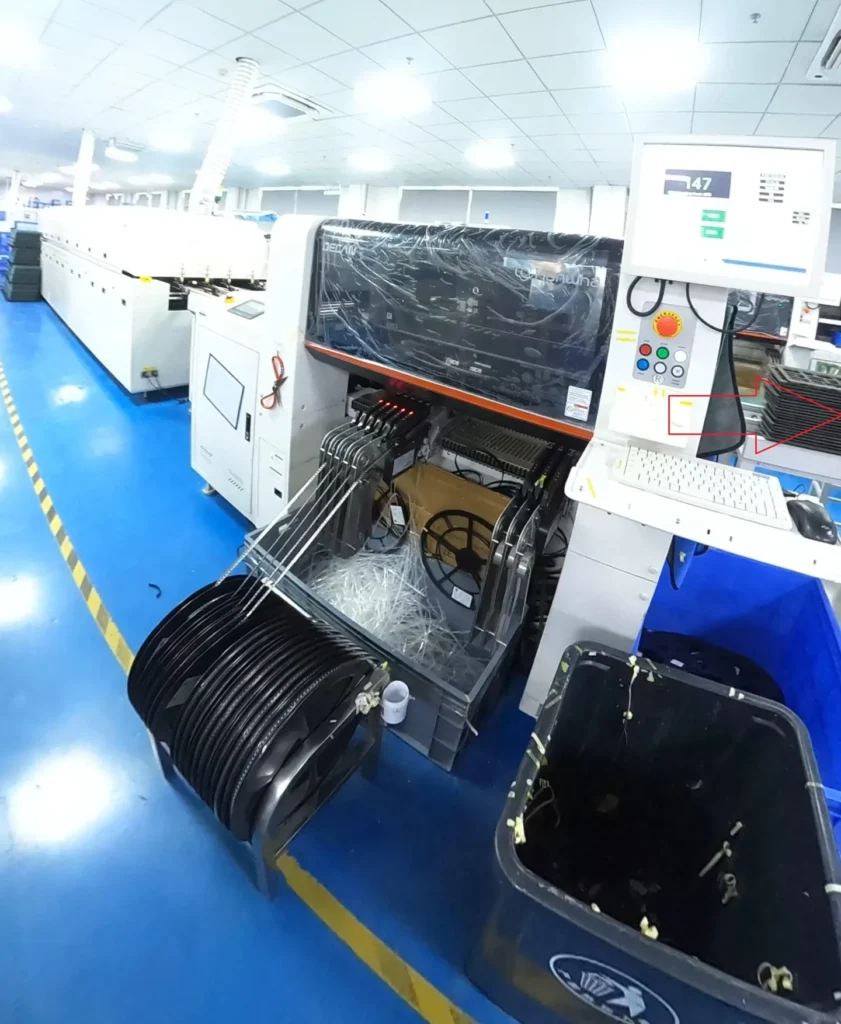
Pick-and-place platforms from Mycronic and other vendors place LED packages at high speed, but placement accuracy only helps if paste is consistent.
Process Control Checks That Prevent Field Failures
| Process step | What to measure | Action to take |
|---|---|---|
| Solder paste | Volume, height, area | Reject boards below target volume |
| Reflow | Peak temperature, time above liquidus | Adjust oven profile before next lot |
| Placement | X/Y offset, angle | Calibrate pick-and-place nozzle |
| Optical test | Brightness, color, dead pixels | Re-bin or recalibrate the module |
| Burn-in | Current draw, temperature | Trace hot spots to solder joints |
3. Match Pixel Pitch to the Real Viewing Distance
One of the most expensive mistakes in LED Display Modules: Manufacturing is choosing a pixel pitch that does not match how far away the screen will be viewed. A 1.2 mm pixel pitch module produces roughly 694,000 pixels per square meter, while a 2.5 mm module produces about 160,000 pixels per square meter.
The finer pitch gives a sharper image, but it increases driver IC count, power density, and PCB registration cost.
The standard viewing-distance rule is simple: minimum comfortable viewing distance in meters is roughly the pixel pitch in millimeters. If most viewers stand 4 meters away, a 4 mm pitch is usually sufficient for smooth video.
A common scenario: an integrator selects 1.5 mm pitch for a lobby screen viewed from 6 meters away, adding thousands in cost without a visible sharpness gain.
How to apply this: Calculate pixel-per-degree from the nearest and farthest viewer positions before the mechanical drawing is finalized.
Cost and Yield Trade-Offs
Finer pitch also narrows the mask bridge between LED pads. Once the gap drops below about 0.15 mm, solder bridging and rework difficulty climb. Production yield often falls as pad spacing shrinks, which can erase the margin gained from charging more for a high-resolution panel.
For high-volume LED Display Modules: Manufacturing, yield loss on fine pitch often erases the premium price.
4. Build Weather Resistance Into the Module Enclosure
Outdoor LED Display Modules: Manufacturing must plan for moisture, UV, thermal stress, and occasional pressure washing. That is why module makers add conformal coating or full potting after SMT assembly and optical test. An IP65-rated enclosure is dust-tight and protected against low-pressure water jets, while IP54 is common for semi-outdoor or under-awning installations.
Conformal coating, usually acrylic, silicone, or polyurethane, seals exposed leads and component bodies. Full potting with thermally conductive silicone adds impact resistance but makes rework much harder. Automated dispensing and coating systems from Nordson are used across electronics production to keep coating thickness consistent. In outdoor LED Display Modules: Manufacturing, coating adhesion matters as much as coating coverage.
How to apply this: Mask connectors and serviceable parts before coating, then run an adhesion test per IPC-CC-830 to verify the coating will not peel.
5. Validate Optical Uniformity Before You Ship
The final gate in LED Display Modules: Manufacturing is optical validation, not just electrical pass/fail. A board can measure no opens or shorts and still show color shift, low brightness, or dead pixels under real drive conditions. Many module datasheets specify brightness uniformity of ±5% or better across the active area, but measurement distance and integration time change the result.
Imaging colorimeters from Radiant Vision Systems or Konica Minolta capture pixel-level luminance and chromaticity data. These tools automate defect detection and produce the uniformity map your QA team needs.
How to apply this: Build an acceptance test plan that samples the corners and center at three brightness levels, not just a single full-white image.
Why Burn-In Testing Still Matters
A 72-hour burn-in cycle at elevated temperature catches infant mortality that a quick electrical test misses. Track current draw and thermal hot spots during burn-in, and map any hot spot back to a solder joint or driver channel before releasing the lot. In mature LED Display Modules: Manufacturing, burn-in is a release gate, not a debugging tool.
Frequently Asked Questions About LED Display Modules: Manufacturing
How long does LED display module manufacturing take from order to shipment?
Lead time for LED Display Modules: Manufacturing usually ranges from three to six weeks, depending on PCB fab time, component availability, and coating or potting cure schedules. Custom shapes, fine pixel pitches, or imported driver ICs can push delivery past eight weeks.
If your project has a fixed install date, lock the BOM and stencil design at least two weeks before PCB release to avoid re-quoting delays.
What is the minimum order quantity for custom LED display modules?
Many contract manufacturers set a minimum order quantity of 50 to 100 pieces for a dedicated SMT run, but that number moves with stencil cost, component reels, and test fixturing. In low-volume LED Display Modules: Manufacturing, using a shared panel design or standard module size lets you combine orders and reduce minimums.
Ask the supplier whether a low-volume prototype run is priced on time-and-materials instead of a per-module rate.
Can a small electronics shop produce LED display modules in-house?
A small shop can handle final assembly, soldering of connectors, and module-level repair, but the core SMT process in LED Display Modules: Manufacturing requires a pick-and-place line with fine-pitch capability. Shops that lack a high-speed line often outsource bare-board assembly and keep coating, wiring, and test in-house.
Verify that the SMT partner has LED-specific experience, because mixed-component boards are not the same as dense LED matrices.
Which certifications matter most for LED display module production?
For LED Display Modules: Manufacturing, ISO 9001 is the baseline quality certificate. UL recognition applies to power and interconnect safety in North America, while CE marking and RoHS compliance are expected in the EU. Some buyers also ask for ETL or TUV marks when modules go into public displays or rental stock.
Confirm which certification applies to the finished module, not just the bare PCB.
Why can two batches of the same module look different in brightness?
LED binning is the main reason two batches of the same module drift apart. LED suppliers sort devices into brightness and color bins, and a cheap batch may mix several adjacent bins. Stable LED Display Modules: Manufacturing locks the bin range in the BOM and runs an aging cycle after assembly.
Request the binning documentation with every incoming LED reel so your optical test baseline stays consistent.
Conclusion
Reliable LED displays start long before the first pixel lights up. The strongest manufacturers control the PCB layout, solder paste deposition, pixel pitch decision, environmental protection, and optical validation as one connected system.
– Design the board for thermal load and IPC class before the first prototype
– Control solder paste volume and reflow profile with SPI and profile checks
– Match pixel pitch to the actual viewer distance, not a spec sheet
– Specify coating or potting based on the installation environment
– Validate brightness and color with calibrated optical tools
Your next step is to audit one module batch from bare board to burn-in. If you produce or buy modules, use the process control table above as a one-page checklist for LED Display Modules: Manufacturing during the next factory visit or supplier review.
Related Articles
- High Resolution Jumbotron Screen with Wide Viewing Angle
- Custom Sizing Options Available for TW VISION Flexible LED Panel Projects
- Choose TW VISION For Reliable Foldable Led Screen Service