

LED Screen Geometry, Native Resolution and Content Mapping: 5 Easy Mapping Secrets

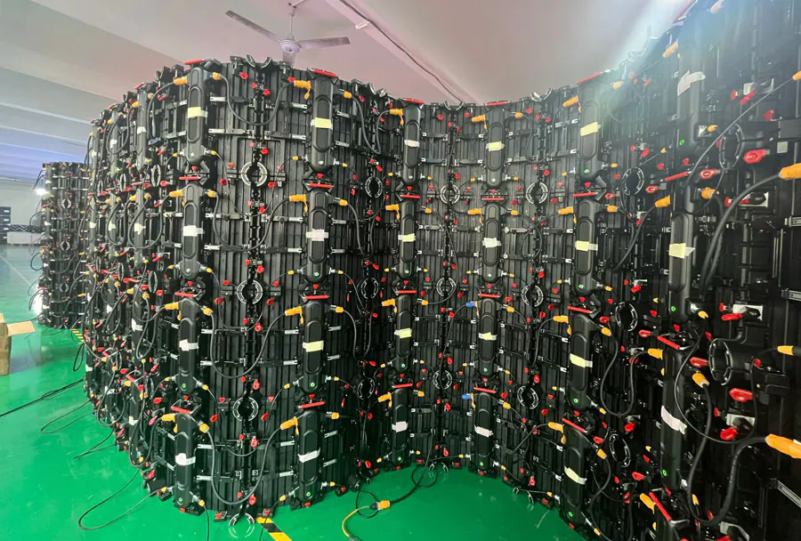
LED Screen Geometry, Native Resolution, and Content Mapping determine whether an LED display looks sharp, aligned, and natural or stretched, cropped, and visibly misregistered. The surprising part is that a high-resolution source cannot correct an incorrectly sized canvas or a cabinet layout that does not match the processor configuration.
Table of Contents
- 1. How LED Screen Geometry Controls the Canvas
- Physical dimensions versus pixel dimensions
- Flat, curved, and irregular surfaces
- 2. How Native Resolution Defines Image Quality
- Calculate the native canvas
- Resolution is not the same as sharpness
- 3. How Content Mapping Prevents Cropping and Distortion
- Logical layout and physical layout
- Use a mapping grid
- 4. Which Tools Help Verify Resolution and Mapping
- Useful tool categories
- 1. Measure the Physical Geometry Before You Build
- Cabinet layout
- Edge and shape checks
- 2. Calculate Native Resolution and Signal Limits
- Source versus canvas
- Bandwidth and scaling
- 3. Map Content to Cabinets and Pixels
- Processor mapping
- Masks and content-safe areas
- 4. Preserve Quality Through Scaling and Processing
- Processor workflow
- Color and brightness
- 5. Verify the Installation With a Repeatable Checklist
- Troubleshooting layers
- How does LED Screen Geometry、Native Resolution and Content Mapping differ from projection mapping?
- What happens when the wall has a nonstandard aspect ratio?
- Can a media server replace an LED processor?
- Why do seams appear even when the map is correct?
- When should content use a lower resolution than the LED wall?
- Conclusion
Many LED problems begin before playback starts: the physical screen may use an unusual aspect ratio, the receiving cards may be mapped in the wrong order, or the content may be rendered at a different pixel size from the display’s native canvas. This guide explains how geometry, resolution, processor mapping, scaling, and testing work together.
You will also learn which measurements to collect, which tools to use, and how to troubleshoot common alignment failures.
1. How LED Screen Geometry Controls the Canvas
LED screen geometry describes the physical shape, pixel dimensions, cabinet arrangement, and viewing orientation of the display. In practice, LED Screen Geometry, Native Resolution and Content Mapping must be planned together because the physical shape determines the correct content canvas.
The first measurement is the total pixel width and height. Multiply the number of cabinets or modules across the screen by the pixel width of each unit, then repeat the calculation vertically. A display built from identical cabinets may still produce a non-standard canvas if the arrangement is wide, tall, curved, or split into multiple surfaces.
Physical dimensions versus pixel dimensions
Physical measurements in metres or feet do not define the content resolution. Pixel pitch affects how many pixels fit into a given physical area, while cabinet dimensions affect how those pixels are arranged.
A smaller pixel pitch usually places more pixels across a similar physical width, but this does not automatically make the display compatible with a particular video source. The processor still needs the exact pixel matrix and receiving-card layout.
Flat, curved, and irregular surfaces
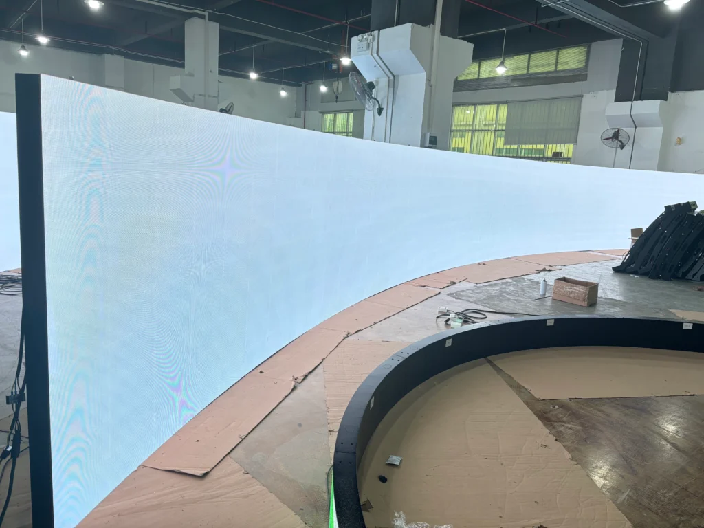
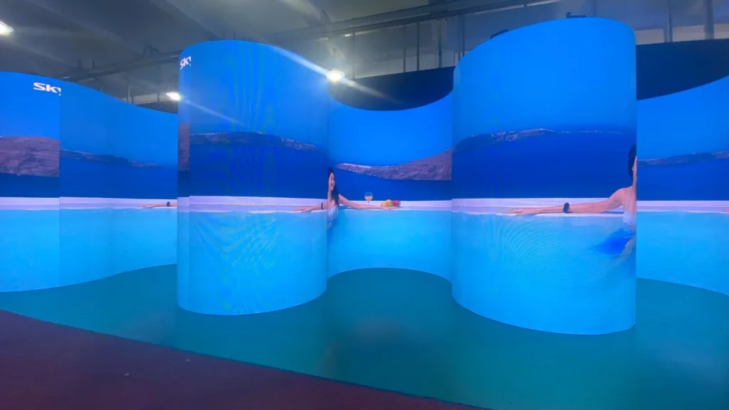
A flat wall is straightforward because each horizontal row normally follows a consistent direction. Curved screens require additional attention because cabinet rotation, receiving-card order, and image compensation can change from one segment to the next.
Consider a 90-degree corner display: a single wide video canvas may need to be divided into separate outputs, even when the two surfaces show one continuous visual. The physical bend is a geometry problem, while the output division is a mapping problem.
The Brompton Technology Tessera documentation explains processor features such as canvas management and scaling that support complex LED installations. Exact capabilities vary by processor model, so use the documentation for the hardware installed at the venue.
How to apply this: Draw the screen from the viewer’s perspective, label every cabinet row and column, and record the pixel width and height of each unit before creating content.
2. How Native Resolution Defines Image Quality
Native resolution is the actual pixel matrix an LED display or processor is designed to show without adding or removing pixels. LED Screen Geometry, Native Resolution and Content Mapping works best when the content canvas matches that matrix exactly.
A source that matches the native canvas can place one source pixel against one display pixel. When the dimensions differ, the processor or media server must scale the image, which can soften fine text, alter proportions, or create cropping.
The ITU-R BT.2020 recommendation defines a consumer television format with a 3840 × 2160 active image area for UHDTV systems. That format is common in production workflows, but an LED wall may have a completely different native canvas, such as 2688 × 768 or 4096 × 1024.
Calculate the native canvas
Use the manufacturer’s module or cabinet specification rather than estimating from the physical size. The basic calculation is:
`total horizontal pixels = cabinet columns × cabinet pixels per cabinet`
`total vertical pixels = cabinet rows × cabinet pixels per cabinet`
In one case, a wall made from 12 cabinets across and 5 cabinets high may produce a 2304 × 960 canvas if each cabinet is 192 × 192 pixels. That canvas is neither 16:9 nor UHD, so a 1920 × 1080 video would require scaling or deliberate cropping.
Resolution is not the same as sharpness
Sharpness also depends on pixel pitch, camera distance, content detail, processing quality, and viewing conditions. A display can have a large pixel count but still show poor results when the source is compressed or the processor uses unsuitable scaling.
How to apply this: Put the calculated native canvas in the production specification and set the media-server composition to those exact width and height values whenever the playback system allows it.
3. How Content Mapping Prevents Cropping and Distortion
Content mapping assigns portions of a source canvas to physical LED outputs, cabinets, modules, or processor inputs. In LED Screen Geometry、Native Resolution and Content Mapping, mapping is the step that connects the design file to the real-world screen.
A correct map answers three questions:
– Which source pixels belong to each output?
– In what order do cabinets and modules receive the signal?
– Which parts of the source are cropped, scaled, rotated, or repeated?
Logical layout and physical layout
The logical layout is how the screen appears in the content software. The physical layout is how data travels through processors, sending cards, receiving cards, and cabinet connections.
These layouts may not match. A screen can look like a simple rectangle while its signal path snakes from one cabinet row to another. If the receiving-card order is wrong, the image may appear reversed, stepped, or displaced even when the source resolution is correct.
Use a mapping grid
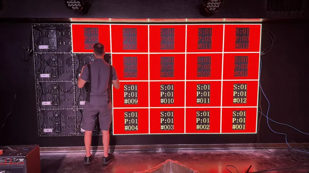
A mapping grid should contain clear labels, horizontal and vertical lines, corner markers, and text large enough to identify the location. Use different colours for each output or region so a swapped connection is immediately visible.
The Resolume Arena and Resolume Arena software pages describe output mapping features for live visual production. Resolume can help divide a composition into output regions, but it does not replace the processor manufacturer’s cabinet and receiving-card configuration.
A common scenario is a screen that displays the correct image on the left but repeats or skips content on the right. This often indicates a width, port, or receiving-card mapping mismatch rather than a problem with the original video file.
How to apply this: Export a labelled grid at the exact native canvas size, display it on the LED wall, and photograph the result so every physical region can be compared with the intended map.
4. Which Tools Help Verify Resolution and Mapping
The right tools reduce guesswork during commissioning. LED Screen Geometry、Native Resolution and Content Mapping should be checked with both software configuration screens and a physical test pattern.
Processor software is used to configure receiving cards, cabinet dimensions, data flow, output canvases, and backup paths. Media-server software controls the content composition, output routing, scaling, and playback. Display-information tools can reveal the source format and handshake data.
Useful tool categories
– Processor configuration software: Brompton Tessera software and NovaStar’s NovaLCT are used for LED processor or receiving-card configuration, depending on the hardware ecosystem.
– Media-server software: Resolume supports composition, layers, output# LED Screen Geometry、Native Resolution and Content Mapping: 5 Easy Secrets
LED Screen Geometry、Native Resolution and Content Mapping determine whether a video wall looks sharp, aligned, and intentional or stretched, cropped, and visibly broken at cabinet seams. A large LED display is not one giant monitor: it is an array of cabinets, receiving cards, processors, pixels, and signal paths that must agree on position and timing.
The main problem is that a wall’s physical shape rarely matches a standard video canvas. A 16:9 source may feed a wide ribbon, a portrait column, or an irregular stage design. This guide explains how to measure the structure, calculate the real pixel canvas, preserve native detail, map content accurately, and test the finished system with practical tools and checklists.
1. Measure the Physical Geometry Before You Build
LED Screen Geometry、Native Resolution and Content Mapping begin with accurate physical measurements, not software settings. Record cabinet width, cabinet height, pixel pitch, cabinet orientation, rows, columns, gaps, masks, and any non-rectangular areas before creating content.
Pixel pitch is the distance from one LED pixel center to the next. If a cabinet is 500 mm wide and uses a 2.5 mm pitch, the horizontal pixel count is approximately 500 ÷ 2.5 = 200 pixels. The same calculation applies vertically, but use the manufacturer’s actual cabinet specification because active pixels may differ from the outside dimensions.
Cabinet layout
Draw the wall as a grid. Label every cabinet from the viewer’s left to right and top to bottom, then mark rotated cabinets and service gaps. This drawing becomes the reference for receiving-card addresses and content coordinates.
A common scenario is a wall made from 12 cabinets across and 4 cabinets high, with each cabinet containing 200 × 200 pixels. Its active canvas is 2,400 × 800 pixels, not a conventional 1,920 × 1,080 canvas.
The physical aspect ratio and the pixel aspect ratio should both be checked because a frame can look proportionally correct on paper yet distort after scaling.
Edge and shape checks
Irregular corners require a content mask or an intentional black area. Do not hide an incorrectly addressed cabinet by cropping the source; first confirm whether the fault is physical placement, data routing, or processor configuration.
How to apply this: Create a cabinet map with dimensions, pixel counts, orientation arrows, and cabinet IDs before anyone configures the processor.
2. Calculate Native Resolution and Signal Limits
Native resolution is the LED wall’s actual pixel grid; it is not automatically the resolution of the laptop, camera, or playback server. LED Screen Geometry, Native Resolution and Content Mapping work correctly when the processor receives a signal that can represent the wall’s intended canvas without avoidable scaling.
Calculate native resolution by multiplying active pixels per cabinet by the number of cabinets in each direction. If the wall is 2,400 × 800 pixels, a 1,920 × 1,080 source cannot fill it without scaling, cropping, unused regions, or a custom output mode.
Source versus canvas
Keep three values separate in your documentation:
– Source resolution: the file or device output, such as 3,840 × 2,160.
– Processing canvas: the composition space used by the media server or switcher.
– Display canvas: the LED wall’s active pixel matrix.
The Video Electronics Standards Association (VESA) describes DisplayPort as a digital display interface designed to carry video and audio between a source and display; its official DisplayPort resources document supported standards and capabilities. That means a connector label alone does not prove that a particular GPU, cable, processor, and refresh-rate combination can carry your required canvas.
Bandwidth and scaling
HDMI’s official specification information identifies HDMI 2.1 features, but practical performance still depends on the source device, certified cable, processor input, and selected timing. Treat every link as a system limit rather than assuming the newest connector guarantees the desired output.
How to apply this: Write the exact source, processor input, output timing, wall resolution, refresh rate, and scaling mode in one signal-flow document, then verify each value during commissioning.
3. Map Content to Cabinets and Pixels
Content mapping assigns each part of an image to the correct physical pixels. In LED Screen Geometry、Native Resolution and Content Mapping, the mapping file is the bridge between the creative canvas and the receiving-card coordinates.
Start with a coordinate system. Define the top-left pixel as 0,0 or 1,1 and use that convention everywhere. Then document whether the processor counts rows from the top or bottom, whether cabinets scan left to right, and whether a cabinet has been rotated.
A single reversed row can make text appear correct in one area while moving graphics in the wrong direction elsewhere.
Processor mapping
Most LED processors use an output canvas and receiving-card configuration. The output canvas describes where data appears in the signal; the receiving-card file describes how that data is distributed through modules and cabinets. These are related but not interchangeable settings.
For complex installations, a media server can divide one composition into mapped slices. Resolume is a real-time audiovisual software platform commonly used for live visuals and compositing; its purpose is creative playback and composition, not replacing the LED processor’s hardware configuration.
Masks and content-safe areas
Use masks for corners, columns, and physical obstructions. Keep critical text away from cabinet seams and avoid placing a thin line exactly on a boundary unless the design intentionally uses that seam.
In one case, a 2,400 × 800 canvas may contain a 200-pixel-wide inactive column. The correct creative canvas can remain 2,400 × 800 while the inactive region is masked, or the layout can be redesigned to use the active area more efficiently; the decision should be documented rather than hidden in an unexplained crop.
How to apply this: Load a numbered cabinet test pattern, confirm each label appears on the intended cabinet, and save screenshots of the final mapping before installing show content.
4. Preserve Quality Through Scaling and Processing
Scaling should be deliberate: either create content at the display canvas or choose a controlled conversion path with known crop, fit, and interpolation behavior. LED Screen Geometry, Native Resolution and Content Mapping fail visually when multiple devices scale the same frame in different ways.
Choose one primary scaler whenever possible. If a switcher scales the source and the LED processor scales it again, fine text and diagonal edges can soften. Match frame rate and timing across the source, processor, and wall, and confirm whether the system uses genlock or another synchronization method when multiple outputs must stay aligned.
Processor workflow
A processor such as a Brompton Tessera system is designed to manage LED display processing and distribution. Brompton Technology provides processor and control-system information; it is not a substitute for checking the LED manufacturer’s module data and receiving-card parameters.
Use test content before judging creative content. Check a one-pixel grid, small text, grayscale ramps, color bars, moving diagonals, and a full-white field. A black level that looks acceptable in a dark room may reveal cabinet brightness differences during a white-field test.
Color and brightness
Do not assume every cabinet has identical calibration. Confirm whether the wall uses factory calibration, a calibration file, or processor-side adjustments. Store the original configuration before changing gain, gamma, refresh, or receiving-card parameters.
How to apply this: Select one scaling device, lock its output timing, and test the wall with grid, grayscale, motion, and color patterns before loading the final media package.
5. Verify the Installation With a Repeatable Checklist
A repeatable commissioning checklist turns LED Screen Geometry、Native Resolution and Content Mapping from a one-time setup into a controlled handover process. Test after installation, after replacing a cabinet, and after changing processor firmware or receiving-card files.
Use a table that separates the symptom from the likely layer. This prevents a content operator from editing a video to compensate for a wiring error or a technician from changing cabinet data to fix a creative crop.
| Check | What it tells you | Action to take |
|---|---|---|
| Cabinet labels | Physical order | Correct placement or IDs |
| Pixel grid | Mapping accuracy | Fix coordinates or rotation |
| Gray ramp | Uniformity | Review calibration |
| Motion pattern | Timing and refresh | Check source and processor |
| White field | Brightness consistency | Inspect modules and calibration |
| Backup file | Recovery readiness | Store dated configuration |
Troubleshooting layers
If an entire cabinet is black, inspect power, data, receiving-card status, and cabinet addressing before changing the media. If only one section is shifted, compare the processor canvas with the saved mapping file. If text is blurry everywhere, check scaling and focus on the source timing rather than re-editing the artwork.
For live events, keep a known-good test file and a copy of the last working configuration offline. Record the processor model, firmware version, receiving-card file, source timing, and wall dimensions in the handover document.
How to apply this: Run the same six checks at every handover, save dated evidence, and require a second person to verify the final cabinet map.
Frequently Asked Questions About LED Screen Geometry、Native Resolution and Content Mapping
How does LED Screen Geometry、Native Resolution and Content Mapping differ from projection mapping?
LED Screen Geometry, Native Resolution and Content Mapping addresses a self-emissive pixel grid, while projection mapping aligns light from a projector with a physical surface. An irregular building facade may need geometric warping and edge blending in projection, whereas an LED wall usually needs cabinet coordinates, masks, and processor mapping.
If both technologies appear in one show, keep their canvases separate and synchronize them through the production system.
What happens when the wall has a nonstandard aspect ratio?
A nonstandard wall can use a custom canvas, letterboxing, cropping, or multiple content zones. LED Screen Geometry, Native Resolution and Content Mapping does not require forcing every asset into 16:9. A very wide banner might display a native-width composition, while a portrait video occupies one defined zone. Document the content rules so operators do not stretch assets to fill unused pixels.
Can a media server replace an LED processor?
Usually, no. LED Screen Geometry, Native Resolution and Content Mapping may involve a media server for playback and slicing, but the LED processor or sending system generally handles output timing, receiving-card communication, and cabinet-level distribution. A small direct-view display may integrate functions differently. Confirm the manufacturer’s architecture before removing hardware from the signal chain.
Why do seams appear even when the map is correct?
Correct mapping cannot remove a physical seam caused by cabinet alignment, module tolerance, brightness variation, or viewing angle. LED Screen Geometry、Native Resolution and Content Mapping helps prove whether the problem is coordinate-related, but a vertical line visible on every source may require mechanical adjustment or calibration. Compare a grid, gray field, and full-white field before changing content.
When should content use a lower resolution than the LED wall?
Lower-resolution content can be appropriate when the source is archival, bandwidth is constrained, or the viewing distance makes additional detail impractical. LED Screen Geometry, Native Resolution and Content Mapping still requires a defined upscale method and crop rule.
For a live camera feed, test motion and fine detail at the venue; a static logo may tolerate scaling that makes fast-moving footage look soft.
Conclusion
A reliable LED wall is designed from its physical pixel grid outward. The most useful habits are:
– Measure cabinets and pixel pitch before creating the canvas.
– Separate source resolution, processing resolution, and display resolution.
– Validate cabinet coordinates with numbered test patterns.
– Test brightness, grayscale, motion, scaling, and recovery files before show day.
LED Screen Geometry, Native Resolution and Content Mapping becomes manageable when every assumption is written down and verified at the correct layer. Start by drawing the cabinet map, calculate the active pixel canvas, choose one scaling path, and run the repeatable commissioning checklist before approving creative content. Use the resulting documentation as the baseline for every future change.
