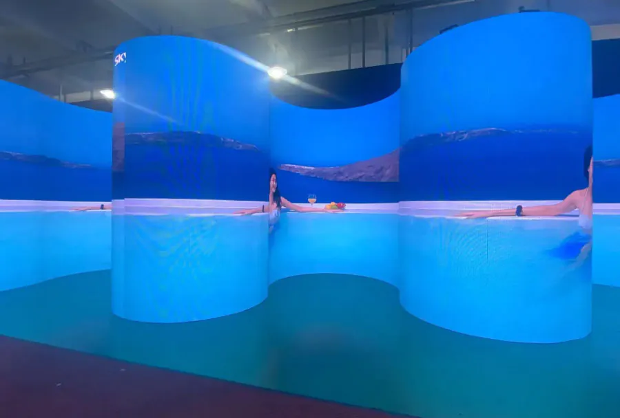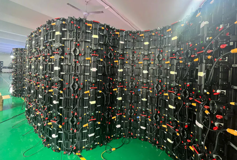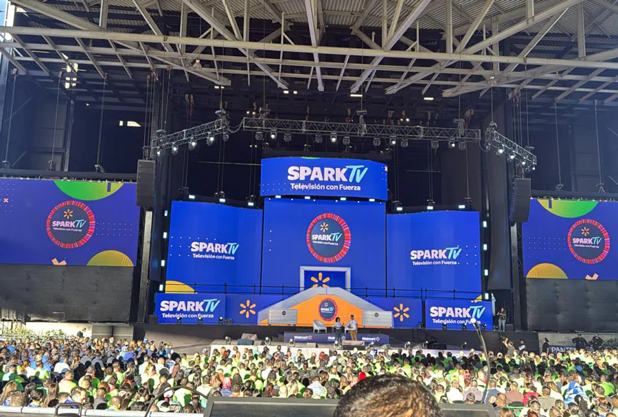
Flexible LED Display Bend Radius: Limits, Risks, and Installation Guidelines

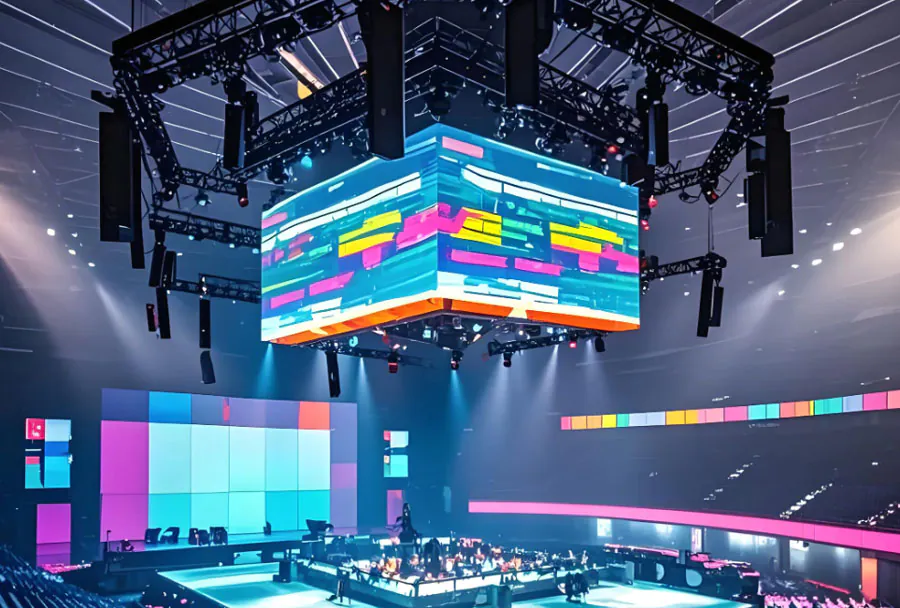
Flexible LED Display Bend Radius: Limits, Risks, and Installation Guidelines begins with one critical fact: there is no universal safe radius for every flexible LED module. The allowable curve depends on the product’s printed circuit board, module thickness, solder joints, masks, connectors, and mounting system.
Table of Contents
- 1. Understand the Minimum Bend Radius
- Radius, Diameter, and Curvature
- Estimate Strain Carefully
- 2. Recognize Mechanical, Electrical, and Thermal Risks
- Mechanical and Electrical Failures
- Heat and Environmental Protection
- 3. Verify the Limit With Documents and Measurement Tools
- Documents to Request
- Tools for Field Verification
- 4. Build and Install the Curve Without Local Stress
- Convert the Design Into Measurable Geometry
- Follow a Controlled Installation Sequence
- 5. Inspect, Commission, and Document the Finished Display
- Run Structured Tests
- Control Hazardous Energy
- How does convex bending differ from concave bending?
- Can flexible LED modules be stored in a curved position?
- What should you do when curved-display seams become uneven?
- Does pixel pitch determine the minimum bend radius?
- What should you do if a module was accidentally overbent?
- Conclusion
A useful engineering relationship is that surface strain rises as bend radius falls. In a simplified model, strain is approximately `ε = t ÷ 2R`, where `t` is thickness and `R` is bend radius. Halving the radius therefore doubles the estimated strain, assuming thickness remains unchanged.
Installers often focus on whether a panel can reach the desired shape, not whether it can remain there through heat cycles, maintenance, and vibration. That mistake can lead to dead pixels, lifted components, damaged power cables, or uneven seams.
The five sections below explain how to interpret bend limits, identify failure risks, verify specifications, build the supporting structure, and commission the finished display safely.
1. Understand the Minimum Bend Radius
The minimum bend radius is the smallest curve a flexible LED product can tolerate under the conditions defined by its manufacturer. Flexible LED Display Bend Radius: Limits, Risks, and Installation Guidelines should therefore be treated as a product-specific engineering requirement, not a general rule of thumb.
Radius, Diameter, and Curvature
Radius is half the diameter of the completed curve. A display wrapped around a column with diameter `D` follows a nominal radius of `D ÷ 2` before allowances for adhesive, brackets, cladding, or module thickness.
Do not confuse the radius of the visible LED surface with the radius of the supporting frame. On a thick assembly, the front surface and rear mounting plane follow different radii.
Curvature can also be expressed as `1 ÷ R`. This means a smaller radius produces greater curvature and higher mechanical demand.
Estimate Strain Carefully
The simplified relationship `ε = t ÷ 2R` helps compare two concepts, but it does not establish an allowable installation limit. Real modules contain multiple materials whose stiffness, neutral axis, and strain tolerance differ.
Consider two otherwise identical assemblies. Reducing the radius from `20t` to `10t` increases the simplified surface-strain estimate from `2.5%` to `5%`. Those calculated values are not permission to bend a real display to either radius; only the manufacturer can define its tested limit.
Flexible LED Display Bend Radius: Limits, Risks, and Installation Guidelines must also distinguish between a one-time installation bend and repeated flexing. A module approved for static curvature may not be rated for continuous movement.
How to apply this: Record the module thickness, support-plane radius, visible-surface radius, bend direction, and manufacturer’s stated minimum before approving the design.
2. Recognize Mechanical, Electrical, and Thermal Risks
Exceeding the approved radius can damage conductors, solder joints, LEDs, masks, connectors, and protective coatings. Flexible LED Display Bend Radius: Limits, Risks, and Installation Guidelines must address these connected failure modes rather than treating curvature as a cosmetic issue.
Mechanical and Electrical Failures
The most common warning signs include:
– Intermittent rows or columns
– Dead pixels near module edges
– Cracked solder joints
– Lifted LEDs or driver components
– Creased flexible circuit material
– Connectors pulling sideways
– Visible gaps between neighboring modules
In the simplified strain model, cutting the radius in half doubles the estimated outer-surface strain. This inverse relationship explains why a seemingly modest last-minute tightening can produce a large increase in mechanical stress.
A common scenario is a cable harness tied tightly across the inside of a concave frame. Even when the LED module remains within specification, the cable or connector may become the weakest component.
Heat and Environmental Protection
Curving a module can reduce contact with its heat-spreading surface or create air gaps behind the display. Uneven heat transfer may then produce local hot spots, color drift, accelerated component aging, or adhesive failure.
Environmental ratings also require care. IEC 60529 defines the IP Code as the classification system for enclosure protection against access, solid objects, and water. An IP rating uses two characteristic numerals, but it does not prove that a curved installation preserves the tested enclosure configuration.
Flexible LED Display Bend Radius: Limits, Risks, and Installation Guidelines should therefore include seals, cable entries, rear covers, and ventilation paths in the risk review.
How to apply this: Inspect the inside and outside of the curve under power, then photograph connectors, seams, masks, and cooling contact points before the display is enclosed.
3. Verify the Limit With Documents and Measurement Tools
The correct bend limit must come from the exact model’s controlled technical documentation or written manufacturer approval. Flexible LED Display Bend Radius: Limits, Risks, and Installation Guidelines cannot rely safely on a reseller image, a specification for a similar model, or the fact that a module bends easily by hand.
Documents to Request
Obtain these records before fabrication:
– Model-specific datasheet and revision number
– Installation manual
– Permitted concave and convex radii
– Static-versus-dynamic bending classification
– Approved mounting-point spacing
– Operating-temperature range
– Warranty exclusions related to bending
– Written approval for unusual geometry
If the document gives only a general statement such as “flexible” or “custom curve,” request a numeric minimum radius and confirmation of where that radius is measured.
Tools for Field Verification
Use measurement and diagnostic tools to confirm that the built structure matches the approved design.
| Tool or record | Purpose | What to check |
|---|---|---|
| Manufacturer drawing | Defines limit | Model and revision |
| Radius template | Checks local curve | Gaps or tight spots |
| Laser meter | Confirms geometry | Chord and offset |
| Thermal camera | Finds hot spots | Uneven temperatures |
| Multimeter | Checks circuits | Voltage and continuity |
A Leica DISTO laser distance meter can measure structural distances used to calculate radius. FLIR ONE thermal cameras connect to compatible mobile devices for infrared inspection, while Fluke thermal cameras provide another way to document temperature patterns during commissioning.
Flexible LED Display Bend Radius: Limits, Risks, and Installation Guidelines should require calibration status where project quality procedures demand traceable measurements.
How to apply this: Create a one-page approval sheet listing the product model, document revision, allowed radius, measured radius, bend direction, and responsible reviewer.
4. Build and Install the Curve Without Local Stress
A safe installation uses a smooth, continuous support surface that keeps every module within its approved curvature. Flexible LED Display Bend Radius: Limits, Risks, and Installation Guidelines should control the frame geometry, fastening sequence, cable routing, and module handling as one coordinated process.
Convert the Design Into Measurable Geometry
For an arc, the relationship is `L = Rθ`, where `L` is arc length, `R` is radius, and `θ` is the angle in radians. Because `90°` equals `π ÷ 2` radians, a quarter-circle with a radius of one metre has an arc length of approximately `1.571` metres.
That calculation is useful for layout, but the fabricated frame must still be checked at several points. A correct average radius can hide a short flat area, sharp transition, proud fastener, or misaligned bracket.
Follow a Controlled Installation Sequence
- Verify the frame radius before installing electronics.
- Remove burrs, weld spatter, and raised fasteners.
- Test-fit non-powered modules without forcing them.
- Start fastening near the center of the arc.
- Work outward in a balanced sequence.
- Keep cables free from tension and pinch points.
- Check seams before final tightening.
- Power the display in controlled stages.
Never use module screws to pull an inaccurate steel or aluminum frame into shape. Fasteners should retain a correctly formed assembly rather than create its curvature.
Flexible LED Display Bend Radius: Limits, Risks, and Installation Guidelines should also account for thermal expansion and service access. A module that can be installed but not removed without excessive bending creates a predictable maintenance hazard.
How to apply this: Perform a full dry fit and mark every location where the module rocks, bridges a gap, or needs force to contact the support.
5. Inspect, Commission, and Document the Finished Display
Commissioning should confirm geometry, image performance, electrical condition, temperature behavior, and maintainability before final handover. Flexible LED Display Bend Radius: Limits, Risks, and Installation Guidelines remain relevant after mounting because defects may appear only when the display heats up or shows demanding content.
Run Structured Tests
Inspect the display in at least three useful operating states:
– Black or low-output content for detecting unwanted glow
– Solid primary colors for identifying pixel and color defects
– High-output content for thermal and power-load assessment
Use the same test content, ambient conditions, measurement locations, and warm-up procedure when creating a thermal baseline. The purpose is not to apply a universal temperature threshold but to find unusual differences between comparable modules.
Record dead pixels, bright pixels, seam alignment, cabinet noise, connector temperatures, power-supply alarms, and control-system errors. If one area runs noticeably hotter, check rear contact, ventilation, current settings, cable terminations, and localized bending.
Control Hazardous Energy
Maintenance must follow applicable electrical and workplace-safety rules. The U.S. Occupational Safety and Health Administration identifies 29 CFR 1910.147 as “The control of hazardous energy (lockout/tagout)” standard.
Do not flex, reseat, or disconnect modules while energized unless the product procedure and applicable safety rules explicitly permit that work. Flexible LED Display Bend Radius: Limits、Risks、and Installation Guidelines should be included in the handover file alongside drawings, test records, photographs, and warranty documents.
How to apply this: Save a commissioning baseline containing radius measurements, test images, thermal scans, defect maps, control settings, and signed acceptance records.
Frequently Asked Questions About Flexible LED Display Bend Radius: Limits、Risks、and Installation Guidelines
How does convex bending differ from concave bending?
Convex and concave curves stress module layers, masks, connectors, and mounted components in opposite directions, so approval for one direction does not automatically cover the other. Flexible LED Display Bend Radius: Limits, Risks, and Installation Guidelines should identify each direction separately.
A module may curve safely around the outside of a column yet interfere with rear components when bent inward, even at the same nominal radius.
Can flexible LED modules be stored in a curved position?
Only if the manufacturer’s storage instructions permit it and the packaging supports the approved radius without concentrated pressure. Flexible LED Display Bend Radius: Limits, Risks, and Installation Guidelines should distinguish storage conditions from operating limits because temperature, stacking loads, and long-term deformation can differ.
A module shipped flat, for instance, should not be rolled tightly into an improvised tube merely to save warehouse space.
What should you do when curved-display seams become uneven?
First determine whether the problem comes from frame geometry, module dimensions, fastener pressure, or thermal expansion rather than hiding it through software calibration. Flexible LED Display Bend Radius: Limits, Risks, and Installation Guidelines require physical alignment to be corrected before image mapping.
One edge that closes only when screws are overtightened usually indicates an inaccurate support surface or a local obstruction behind the module.
Does pixel pitch determine the minimum bend radius?
Pixel pitch alone does not determine the minimum radius because circuit construction, component placement, mask geometry, module thickness, and mounting design also matter. Flexible LED Display Bend Radius: Limits, Risks, and Installation Guidelines should use the exact model specification instead.
Two products with the same pixel pitch may have different bending capabilities, especially when one uses segmented rigid boards and the other uses a continuous flexible circuit.
What should you do if a module was accidentally overbent?
Disconnect it safely, quarantine it, record the incident, and ask the manufacturer whether inspection or replacement is required. Flexible LED Display Bend Radius: Limits, Risks, and Installation Guidelines should not assume that returning the module to its original shape removes hidden damage.
An overbent unit may pass an immediate image test but later develop intermittent conductors, cracked solder joints, delamination, or weakened protective coatings.
Conclusion
A flexible LED display is safe only when its modules, frame, wiring, cooling, and maintenance method all support the specified curve. Flexible LED Display Bend Radius: Limits, Risks, and Installation Guidelines should be documented from design approval through final commissioning.
Key takeaways include:
– Use the exact manufacturer limit, including bend direction and measurement plane.
– Never force modules onto an inaccurate frame or use fasteners to create the curve.
– Inspect electrical, mechanical, thermal, and environmental risks together.
– Preserve measurements, thermal images, test content, and approval records.
Your next step is to obtain the model-specific installation manual, calculate the proposed geometry, and build a radius template before fabrication begins. If any limit is unclear, secure written manufacturer approval rather than relying on an estimate.