Revealing Curved Surface Correction and Irregular Content Adaptation Technology of TW VISION Custom Shape LED Screens

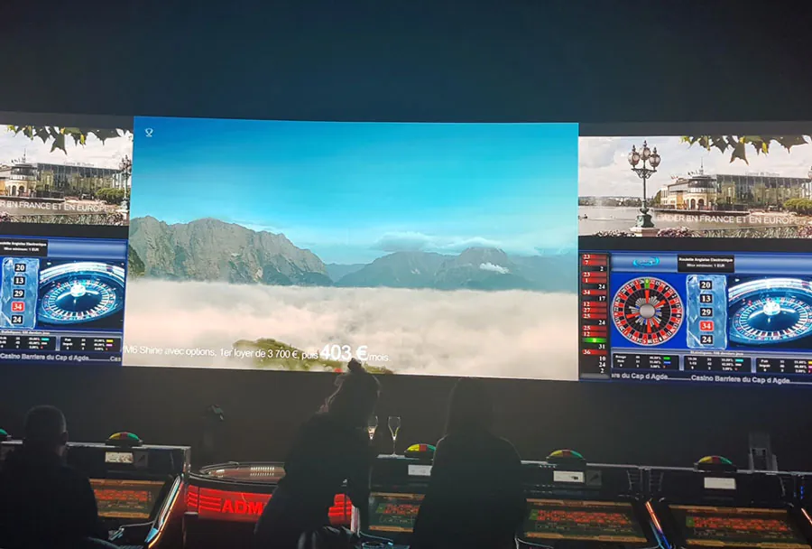
In the dynamic world of digital display solutions, the demand for moving beyond flat, rectangular screens has surged. Architects, event producers, and brand experience designers seek to blend digital canvases seamlessly into unconventional spaces and structures. This is where custom-shaped LED screens, particularly those with curved and irregular geometries, become paramount. TW VISION has emerged as a leader in this niche, not merely by manufacturing unique physical panels, but by mastering the sophisticated software technologies that make them work: Curved Surface Correction and Irregular Content Adaptation. This article explains these core technologies, their function and importance, and how they establish TW VISION’s authority in creating immersive visual experiences.
The Challenge: From Flat Pixels to a Cohesive Curved Canvas
A standard LED wall is a grid of pixels—orderly, predictable, and flat. When you bend this grid, either into a gentle curve or a complex 3D shape, a fundamental problem arises: geometric distortion. From the viewer’s perspective, pixels are no longer at a uniform distance or angle. A simple image designed for a flat surface, if projected directly onto a curved screen, would appear stretched at the edges and compressed in the center, breaking immersion and clarity.
This is the primary challenge TW VISION’s technology addresses. It’s not enough to simply build flexible modules; the true innovation lies in digitally “correcting” the content so it appears perfectly proportioned on the non-flat surface. This process is known as Curved Surface Correction, or more technically, surface mapping and warping.
Core Technology I: Advanced Curved Surface Correction (Surface Mapping & Warping)
TW VISION’s Curved Surface Correction technology is a multi-step computational process that ensures visual integrity. It begins with precise 3D modeling of the physical installation. Every panel’s position, orientation, and curvature in 3D space are meticulously measured and mapped within a software environment, creating a digital twin of the screen.
The core of the correction lies in the warping algorithm. This algorithm mathematically calculates the distortion for every single pixel on the curved surface relative to a virtual “flat” source image. It then generates a correction map—essentially a set of instructions that tells the video processor how to pre-distort the original content. When this pre-distorted content is displayed on the physically curved screen, the two distortions cancel each other out, resulting in a perfectly natural-looking image for the viewer.
TW VISION’s expertise is evident in the granularity and real-time capability of this system. Their technology handles:
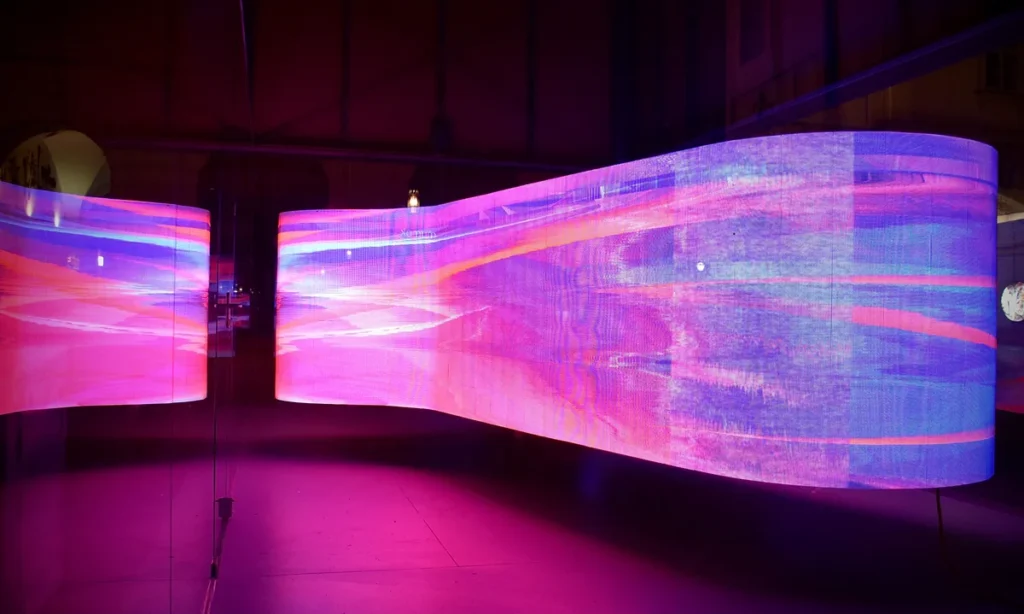
Complex Compound Curves: Seamlessly blending concave, convex, and S-curves within a single display.
Pixel-Level Accuracy: Ensuring no blurring or “ghosting” at the seams between modules, even on tight radii.
Real-Time Processing: Allowing for live video feeds and interactive content to be displayed without lag, crucial for broadcasts and live events.
This sophisticated correction forms the foundational layer, making the curved screen a viable canvas. The next step is to creatively exploit that unique canvas.
Core Technology II: Intelligent Irregular Content Adaptation
Once the screen is geometrically corrected, it presents a new opportunity: content that doesn’t just fit the shape but interacts with it. This is the domain of Irregular Content Adaptation. While surface correction ensures a standard video looks right, content adaptation involves designing or modifying media specifically to enhance the shape’s impact.
TW VISION provides tools and expertise for two primary approaches:
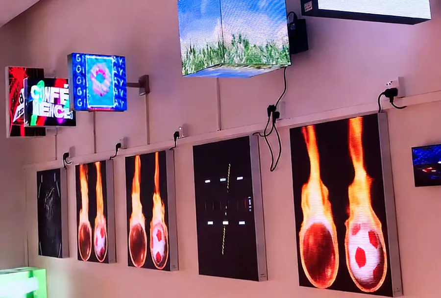
1. Masking & Edge Blending: For screens with non-rectangular silhouettes (like circles, logos, or wave shapes), content is crafted with transparent backgrounds or soft edges that blend into the environment, making the screen’s shape the focal point rather than a containing rectangle.
2. 3D Content Mapping & Perspective Locking: This is the pinnacle of adaptation. Here, 3D animations or visuals are created with the screen’s exact 3D model as a reference. Content can appear to flow around corners, erupt from a specific vertex, or maintain a fixed perspective from a key audience viewpoint. For instance, a product reveal might show a car driving along the path of a curved screen, with the perspective perfectly locked so the car’s size and motion feel physically authentic.
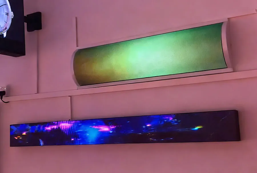
TW VISION’s technology stack supports standard formats like Maya, 3DS Max, and Notch for content creation, allowing creators to work within familiar professional ecosystems. Their playback systems can then interpret the spatial data, ensuring the pre-rendered or real-time content aligns pixel-perfectly with the physical display.
How to Test Geometric Distortion on a Custom Shape LED Screen
1. Document the Screen Geometry and Signal Path
Begin by recording the intended pixel map, physical shape, and complete signal path before judging the image. How to Test Geometric Distortion on a Custom Shape LED Screen depends on knowing what the display is supposed to reproduce.
Build a Coordinate Manifest
Create a manifest with four core fields for every cabinet or module:
– Logical pixel coordinates
– Physical position and orientation
– Receiving-card or processor assignment
– Active and intentionally unused pixels
A custom display may contain black pixels in its source canvas that do not correspond to physical LEDs. Treating those areas as missing content will produce false distortion findings.
Trace the Image Pipeline
Document the route from the content canvas through the media server, scaler, LED processor, receiving cards, and modules. Record where scaling, rotation, cropping, or warping is enabled.
Consider a triangular section rotated inside a rectangular processor canvas. If the media server and processor both rotate that section, the resulting error is a configuration problem rather than panel deformation.
Use Resolume Arena when you need a visual output map for routing and transforming content across irregular display regions. Its input and output mapping views can help you compare the content layout with the processor map.
Before continuing How to Test Geometric Distortion on a Custom Shape LED Screen, save screenshots or exports from every mapping stage so that later changes remain traceable.
How to apply this: Create a one-page coordinate manifest today and mark every scaling, rotation, crop, and warp operation in the signal path.
2. Generate Test Patterns That Expose Different Errors
Use several high-contrast patterns because no single image reveals every type of geometric distortion. How to Test Geometric Distortion on a Custom Shape LED Screen works best when each pattern has one diagnostic purpose.
Use a Small Pattern Set
Prepare at least these three pattern types as part of your project test protocol:
– Orthogonal grid: Reveals bending, uneven scaling, and discontinuities between modules.
– Concentric circles: Exposes nonuniform horizontal and vertical scaling.
– Coordinate markers: Identifies swapped, rotated, duplicated, or incorrectly cropped regions.
Add diagonal lines when cabinet seams or curved transitions could hide errors from horizontal and vertical lines. Include an outline that follows the intended physical boundary of the screen.
Keep Patterns Pixel-Accurate
Create the patterns at the processor’s native canvas resolution. Disable antialiasing for one-pixel reference lines, and avoid compressed image formats that may soften edges or add ringing.
A practical pattern can label major intersections with their source coordinates. If a label assigned to the upper-left region appears near the center, you immediately know that the problem involves routing or transformation rather than subtle physical distortion.
TouchDesigner can generate procedural grids, circles, coordinate labels, and animated sweeps at a defined output resolution. Animation is useful for finding duplicated or frozen receiving-card regions.
Run How to Test Geometric Distortion on a Custom Shape LED Screen with all content effects, motion blur, and decorative masks disabled.
How to apply this: Export a native-resolution test package containing a grid, circles, diagonals, edge outlines, and labeled coordinates.
3. Control the Camera and Viewing Position
Capture the display from a documented reference position so perspective and lens distortion do not contaminate the result. When you perform How to Test Geometric Distortion on a Custom Shape LED Screen, an uncontrolled photograph can make a correctly mapped display look defective.
Choose the Correct Reference View
For a flat screen, place the camera near the screen’s perpendicular centerline when the installation allows it. Keep the full display in frame without using an unnecessarily wide focal length.
For a curved or faceted screen, use the project’s designated audience viewpoint. The image may be intentionally distorted elsewhere so that it appears correct from that location.
Record the following capture conditions:
– Camera position and height
– Lens and focal length
– Image resolution
– Focus and exposure settings
– Distance or surveyed location
– Intended audience reference point
Calibrate the Lens
Lens distortion can bend grid lines near the frame edges. OpenCV provides checkerboard-based camera calibration and functions for removing radial and tangential lens distortion.
OpenCV’s official calibration tutorial states, “For better results, we need at least 10 test patterns.” Those images should show the calibration target at different positions and orientations, not ten copies from an unchanged viewpoint.
A common scenario is a straight screen photographed with a wide-angle lens. Curved lines appearing mainly near the photograph’s outer edges often indicate lens distortion rather than an LED mapping fault.
Complete camera calibration before using photographs for How to Test Geometric Distortion on a Custom Shape LED Screen.
How to apply this: Mark the reference camera position on the floor and capture a calibrated image set with fixed focus, zoom, and exposure.
4. Measure Displacement Instead of Relying on Sight
Measure reference-point displacement against the intended geometry to turn visual impressions into repeatable findings. How to Test Geometric Distortion on a Custom Shape LED Screen should produce coordinates and error values, not comments such as “the corner looks stretched.”
Calculate Point and Line Error
For each visible grid intersection, compare its measured position with the expected position after applying the approved projection. Record horizontal and vertical error as:
– `Δx = measured x − expected x`
– `Δy = measured y − expected y`
– `Total displacement = √(Δx² + Δy²)`
Use signed values for `Δx` and `Δy`. The direction helps identify whether an area is shifted, scaled, rotated, or warped.
Classify the Error Pattern
| Observation | Likely cause | Action to take |
|---|---|---|
| Constant offset | Position error | Shift the region |
| Error grows across width | Scale mismatch | Correct horizontal scale |
| Error changes by angle | Rotation error | Check transform origin |
| Local jump at seam | Cabinet mapping | Inspect adjacent modules |
| Curved outer lines | Lens or warp | Calibrate camera or warp |
In one case, a point expected at `(800, 400)` but measured at `(806, 392)` has `Δx = +6` and `Δy = −8`. The total displacement is `10` pixels by the Pythagorean formula, but the signed components remain more useful for correction.
Repeat How to Test Geometric Distortion on a Custom Shape LED Screen with several distributed points so a local defect is not mistaken for a screen-wide transformation.
How to apply this: Enter expected and measured coordinates into a spreadsheet, calculate signed displacement, and plot the errors by screen region.
5. Correct One Layer at a Time and Verify the Result
Correct the earliest incorrect stage in the signal path, then rerun the same test without changing the capture conditions. How to Test Geometric Distortion on a Custom Shape LED Screen becomes unreliable when several transformations are adjusted simultaneously.
Follow a Correction Order
Review potential causes in this order:
- Source canvas dimensions and content coordinates
- Media-server output mapping
- Scaler or switcher settings
- LED processor cabinet mapping
- Physical cabinet position
- Deliberate perspective warp
This sequence prevents a downstream warp from hiding an upstream mapping error. Physical adjustment should not compensate for a duplicated pixel region, and content distortion should not conceal a misaligned cabinet.
Define Acceptance Before Sign-Off
There is no universal pixel-error threshold for every custom LED installation. The acceptable limit depends on pixel pitch, viewing distance, physical shape, camera use, and whether the image is optimized for one audience position.
Use three documented result states: pass, correctable configuration issue, and physical review required. Store the source pattern, processor configuration, calibrated photograph, coordinate measurements, correction history, and final approval together.
Suppose a corrected grid passes from the audience reference point but looks stretched from a side corridor. That can be acceptable for anamorphic content if the project specification clearly identifies the primary viewpoint.
Finish How to Test Geometric Distortion on a Custom Shape LED Screen by restoring each creative effect individually and confirming that it does not reintroduce an unintended transformation.
How to apply this: Lock the approved test files and configurations, then create a signed baseline package for future maintenance comparisons.
Establishing Authority: The TW VISION Ecosystem and Real-World Applications
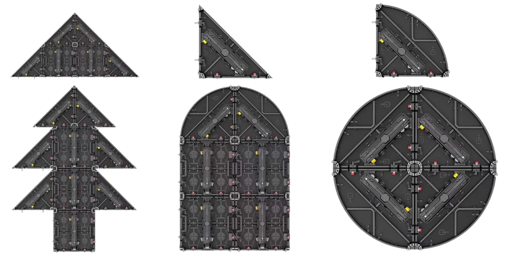
TW VISION’s authority in this field is built on a holistic ecosystem that integrates hardware, software, and expert support. Their custom shaped LED screens—including triangle, hexagon, curved, and flexible options—are engineered to precise tolerances, providing the reliable physical substrate for their software magic.
This technological prowess translates into transformative applications:
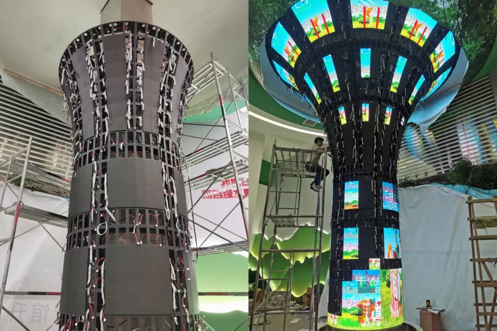
Architectural Integration: Blending curved LED columns, domes, or ceilings into lobbies, museums, and retail spaces, where correction ensures legibility and adaptation creates ambient, shape-following art.
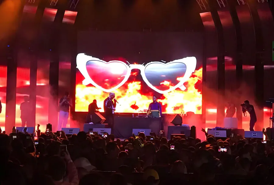
Immersive Entertainment: Creating wrap-around stages for concerts and theater-in-the-round experiences where every audience member gets a correct, engaging view.
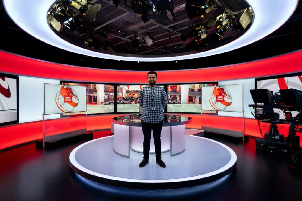
Corporate & Broadcast: Designing iconic keynote backdrops and virtual studios where content dynamically interacts with the set’s unique geometry, enhancing brand messaging.
Simulation & Control Rooms: Employing curved video walls that provide a continuous, distortion-free field of view for pilots, operators, or traffic controllers.
The Synergy of Form and Intelligence
The true value of TW VISION’s custom shape LED solutions is not found in the individual panels, but in the intelligent technology that unlocks their potential. Curved Surface Correction is the essential, behind-the-scenes genius that solves the physics problem of distortion, establishing a flawless visual baseline. Irregular Content Adaptation is the creative frontier that leverages unique shapes to tell more powerful, immersive stories.
Together, these technologies demonstrate a deep Expertise, Experience, Authoritativeness, and Trustworthiness (EEAT). They show an understanding of complex optical science, proven experience in challenging installations, authoritative command over the software-hardware pipeline, and a trustworthy commitment to delivering the promised visual outcome. For anyone looking to push the boundaries of digital display beyond the rectangle, understanding and leveraging these core technologies is not an option—it is the very foundation of success. TW VISION’s solutions stand as a testament to this principle, revealing how intelligent software transforms innovative hardware into captivating visual experiences.
Frequently Asked Questions About How to Test Geometric Distortion on a Custom Shape LED Screen
How do I test a transparent LED screen when the background interferes?
Place a matte, neutral backing behind the display when site conditions permit, then use high-contrast lines that remain visible through the panel structure. How to Test Geometric Distortion on a Custom Shape LED Screen becomes harder when background architecture creates false edges.
If a backing cannot be installed, capture the test after dark or temporarily reduce background lighting while keeping the display settings documented.
What should I do if moiré hides the grid in camera footage?
Change the camera distance, focal length, or aperture without moving away from the documented viewing axis. Moiré is an interaction between the LED pixel structure and camera sensor sampling; it is not geometric deformation. During How to Test Geometric Distortion on a Custom Shape LED Screen, retain at least one sharp still image.
A slightly different camera position may suppress moiré while preserving useful reference geometry.
Can geometric distortion be tested while the screen is moving?
Yes, but first establish a valid result at each fixed mechanical position. How to Test Geometric Distortion on a Custom Shape LED Screen with kinetic panels requires synchronized records of panel position, timecode, and displayed pattern. A screen may pass while stationary but fail during motion because of delayed position data, flexible cabling, or mechanical play.
Use repeated stops to separate motion-related errors from mapping faults.
How should I handle missing or dead pixels during measurement?
Exclude isolated dead pixels from geometric calculations unless they prevent you from locating a reference intersection. How to Test Geometric Distortion on a Custom Shape LED Screen focuses on position, scale, rotation, and shape rather than pixel-health classification.
If an entire row or module is inactive, postpone measurement in that region because the missing visual reference can conceal a mapping shift or create an incorrect edge.
Why does the test pass live but fail in recorded video?
The camera may introduce rolling-shutter artifacts, frame-rate mismatch, stabilization, or lens correction that is absent to the eye. How to Test Geometric Distortion on a Custom Shape LED Screen for broadcast use should include the production camera chain, not only a visual inspection. Disable digital stabilization and undocumented in-camera geometry correction first.
Then compare a still frame with the live display before changing the LED configuration.
Conclusion
A defensible distortion test separates the source map, processing chain, physical display, camera, and intended viewpoint. The final result should be measurable and repeatable rather than based on visual preference alone.
– Document the native canvas, module coordinates, and every transformation.
– Use grids, circles, diagonals, boundaries, and coordinate markers.
– Calibrate the camera and preserve the approved viewing position.
– Measure signed displacement, correct one layer, and save the baseline.
How to Test Geometric Distortion on a Custom Shape LED Screen is ultimately a controlled comparison between intended and observed geometry. Start by creating the coordinate manifest and native-resolution pattern package, then capture your first calibrated baseline before changing any processor, mapping, or cabinet setting.