How to Build a Spare Parts Plan for an LED Display: Modules, Power Supplies and Receiving Cards

How to Build a Spare Parts Plan for an LED Display: Modules, Power Supplies and Receiving Cards starts with one practical fact: an LED wall can remain partly functional while still showing visible defects that require several different replacement parts. A failed module may look like a power problem, while a damaged receiving card can affect an entire cabinet.
Table of Contents
- 1. Map the Display Before Buying Spares
- Build a compatibility record
- 2. Set Stock Levels by Failure Impact
- Use a risk score
- 3. Calculate Module, Power-Supply, and Card Quantities
- 4. Control Compatibility, Firmware, and Configuration
- 5. Store, Test, and Review the Spare Inventory
- How should I plan spares for a rental LED display?
- Can I use a higher-wattage power supply as a replacement?
- What should I do with discontinued receiving cards?
- How can I diagnose a dark cabinet before replacing the receiving card?
- Should spare modules be calibrated before storage?
- Conclusion
In How to Build a Spare Parts Plan for an LED Display: Modules, Power Supplies and Receiving Cards, the challenge is deciding what to stock, how many units to hold, and which parts are truly compatible. Buying too little creates long outages; buying too much ties up cash in parts that may become obsolete when the display is upgraded.
This guide explains how How to Build a Spare Parts Plan for an LED Display: Modules、Power Supplies and Receiving Cards works in practice. It covers failure points, spare quantities, compatibility, storage, documentation, control software, electrical testing, supplier records, and field feedback.
1. Map the Display Before Buying Spares
How to Build a Spare Parts Plan for an LED Display: Modules, Power Supplies and Receiving Cards begins with a complete hardware map, including the LED modules, power supplies, receiving cards, data cables, cabinets, controller, and internal wiring. This inventory should identify both the part number and the exact location of each component.
Start by recording the display’s physical and electrical configuration:
– Cabinet width and height
– Module dimensions and pixel pitch
– Module scan mode
– LED driver IC model
– Receiving-card model and firmware family
– Power-supply output voltage and rated wattage
– Data-cable type and connector layout
– Controller or sending-card model
– Indoor or outdoor protection requirements
In How to Build a Spare Parts Plan for an LED Display: Modules, Power Supplies and Receiving Cards, a module’s physical size is not enough to confirm compatibility. Two modules can share the same dimensions but use different pinouts, scan modes, driver chips, or hub-board connections.
Build a compatibility record
For How to Build a Spare Parts Plan for an LED Display: Modules, Power Supplies and Receiving Cards, use a spreadsheet or asset-management system with one row per component. Include a photograph of the installed part, the supplier part number, and the date of the last confirmed purchase.
| Part | Compatibility evidence | What to check |
|---|---|---|
| LED module | Size, pitch, scan, pinout | Compare with a working module |
| Power supply | Voltage, wattage, terminals | Confirm label and load |
| Receiving card | Model, ports, firmware | Export controller settings |
| Hub board | Connector layout | Match cabinet revision |
| Data cable | Length and connector type | Test continuity |
The NovaStar control-system ecosystem is commonly used with LED sending and receiving hardware, but the software and firmware must still match the installed card family. In How to Build a Spare Parts Plan for an LED Display: Modules, Power Supplies and Receiving Cards, never assume that a visually similar card is interchangeable.
According to IEC 60529, an IP code communicates protection against solids and water ingress. That matters when replacing an outdoor cabinet component because a substitute with a different enclosure or sealing arrangement can change the display’s environmental protection.
How to apply this: photograph every installed component, copy every label into a master inventory, and mark each item as directly compatible, conditionally compatible, or unverified.
2. Set Stock Levels by Failure Impact
In How to Build a Spare Parts Plan for an LED Display: Modules、Power Supplies and Receiving Cards, the right quantity of spares depends on failure impact, replacement lead time, installed quantity, and the consequences of downtime. A busy roadside display usually deserves a different plan from a small indoor lobby screen.
A useful starting point is to classify parts into three groups:
– Immediate-failure parts: modules, data cables, fuses, and common connectors
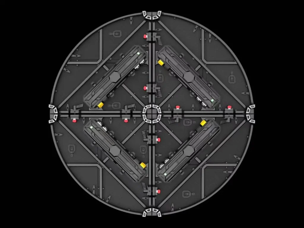
– System-critical parts: receiving cards, sending cards, hub boards, and power supplies
– Low-frequency parts: cabinet frames, specialized interface boards, and discontinued components
For How to Build a Spare Parts Plan for an LED Display: Modules, Power Supplies and Receiving Cards, the most important principle is to stock the parts that can disable the largest visible area. A failed receiving card may affect an entire cabinet, while one failed module normally affects only a small section.
Use a risk score
How to Build a Spare Parts Plan for an LED Display: Modules, Power Supplies and Receiving Cards uses four main risk factors:
– Number installed
– Failure frequency
– Supplier lead time
– Operational impact
A simple five-point score for each factor is enough for a first plan. The total does not predict failure; it helps you rank purchasing priority.
Consider a display with several cabinet types and one receiving-card model used across all of them. Even if receiving cards fail less often than modules, the shared model may deserve priority because one card can interrupt a larger section and may require firmware-specific replacement.
Mean Well’s official product documentation shows that power-supply families can differ substantially in rated output, input range, cooling method, and protection features. The label and datasheet should therefore be treated as the source of truth, rather than a seller’s abbreviated listing.
How to apply this: create a four-factor risk score for every part and buy the highest-risk items first, beginning with parts that can disable an entire cabinet or section.
3. Calculate Module, Power-Supply, and Card Quantities
How to Build a Spare Parts Plan for an LED Display: Modules, Power Supplies and Receiving Cards combines a minimum operating reserve with a lead-time reserve. The calculation should use your own maintenance records because environmental conditions, operating hours, installation quality, and component age vary widely.
For How to Build a Spare Parts Plan for an LED Display, count the modules installed and identify whether one spare can be used across multiple cabinet revisions. Keep spare modules protected from moisture, static discharge, dust, and mechanical damage.
Within How to Build a Spare Parts Plan for an LED Display, record the output voltage and wattage printed on every power supply. A replacement with higher wattage is not automatically safe if its voltage, terminal arrangement, protection behavior, or mounting dimensions differ.
For receiving cards requires at least one tested spare for each distinct model and firmware family that cannot be replaced by another approved model. A spare card should be labeled with its current configuration status.
A simple planning worksheet can use these fields:
– Installed quantity
– Average failures recorded
– Average supplier lead time
– Number of compatible models
– Criticality of failure
– Current usable stock
– Minimum reorder level
The Fluke website identifies digital multimeters as instruments for measuring electrical values such as voltage, current, and resistance. A multimeter cannot validate every LED-system fault, but it can help technicians check supply voltage and continuity before replacing a module or card.
In one case, a maintenance team may discover that several “module failures” were actually caused by loose power terminals. Recording the diagnostic result prevents the organization from inflating module stock while ignoring wiring inspections.
How to apply this: calculate quantities from installed counts and actual failure records, then test every spare power supply and receiving card before placing it into emergency stock.
4. Control Compatibility, Firmware, and Configuration
Hardware compatibility is only one part of How to Build a Spare Parts Plan for an LED Display. A replacement receiving card can be electrically correct and still produce incorrect colors, scan errors, image offsets, or a blank cabinet if its configuration is wrong.
For How to Build a Spare Parts Plan for an LED Display, maintain a configuration archive containing:
– Cabinet resolution
– Module width and height
– Scan mode
– Data group arrangement
– Color order
– Driver-chip settings
– Receiving-card address
– Firmware version
– Brightness and calibration files
– Sending-card and controller settings
How to Build a Spare Parts Plan for an LED Display also requires you to export the current configuration before changing a card. Save it with the display’s asset record and label the file with the site, cabinet number, card model, and export date.
NovaStar’s control platforms are designed to configure and manage LED display systems, but available functions differ by product and firmware. Keep the software version used for commissioning alongside the configuration file so a technician can reproduce the setup during an outage.
A common scenario is that a replacement card powers on normally but displays a scrambled image because the receiving-card mapping does not match the cabinet’s physical data path. This is a configuration problem, not proof that the card is defective.
The U.S. Occupational Safety and Health Administration states that employers must provide a workplace free from recognized hazards. In practice, technicians should isolate power, follow site procedures, use appropriate personal protective equipment, and avoid treating a live cabinet as a diagnostic bench.
How to apply this: export and verify one known-good configuration file per cabinet type, then attach it to the corresponding spare-card label and service record.
5. Store, Test, and Review the Spare Inventory
How to Build a Spare Parts Plan for an LED Display must account for whether each part can be located, identified, and installed without creating a second failure. Storage conditions and testing routines therefore belong in the spare-parts plan.
Use separate storage areas for tested, untested, failed, and repair-pending items. For How to Build a Spare Parts Plan for an LED Display: Modules、Power Supplies and Receiving Cards, every item should have an inventory label showing:
– Part number
– Compatible display or cabinet
– Quantity
– Test status
– Date received
– Last test date
– Supplier
– Firmware or configuration status
How to Build a Spare Parts Plan for an LED Display requires electrostatic-discharge precautions when handling modules and control cards. Keep packaging intact when possible, and protect parts from condensation, crushing, dust, and uncontrolled temperature changes.
Test procedures should match the part:
– Power supplies: visual inspection, output-voltage check, and terminal inspection
– Modules: test pattern, brightness consistency, and connector inspection
– Receiving cards: bench test with an approved cabinet or simulator
– Data cables: continuity and connector retention check
– Hub boards: connector and signal-path inspection
For How to Build a Spare Parts Plan for an LED Display: Modules、Power Supplies and Receiving Cards, review the inventory after every service call. Replace consumed stock immediately, investigate repeated failures, and remove obsolete parts from the active count.
A documented inspection cycle is more valuable than an arbitrary replacement interval because it connects stock decisions to real operating evidence. Record whether a component failed from age, heat, moisture, loose wiring, handling damage, or an upstream fault.
How to apply this: run a monthly inventory check, test every emergency spare on a defined schedule, and open a corrective-action record when the same part fails repeatedly.
Frequently Asked Questions About How to Build a Spare Parts Plan for an LED Display: Modules、Power Supplies and Receiving Cards
How should I plan spares for a rental LED display?
Rental displays need a transport-focused plan as well as an electrical one. Include spare module masks, corner protectors, latches, power and data cables, and cabinet hardware because repeated assembly can damage mechanical parts even when electronics remain healthy.
How to Build a Spare Parts Plan for an LED Display: Modules、Power Supplies and Receiving Cards should account for the number of daily builds, transport distance, and event changeover time.
Can I use a higher-wattage power supply as a replacement?
Not without confirming voltage, output polarity, terminals, mounting, protection behavior, and approval from the equipment manufacturer or qualified engineer. A higher wattage rating does not correct an incorrect output voltage or incompatible connector.
In How to Build a Spare Parts Plan for an LED Display, classify higher-rated substitutes as conditional until they pass a documented compatibility review.
What should I do with discontinued receiving cards?
Keep a tested reserve only when the installed system cannot accept a current replacement without a controller or firmware change. Also preserve the original configuration files and document the migration path.
A discontinued card may be valuable for an older sign, but How to Build a Spare Parts Plan for an LED Displayshould separate legacy stock from parts approved for current installations.
How can I diagnose a dark cabinet before replacing the receiving card?
Check incoming mains isolation procedures, power-supply output, fuse condition, cabinet indicators, data-cable seating, and controller status first. A dark cabinet may result from lost power or signal rather than a failed receiving card.
During How to Build a Spare Parts Plan for an LED Display, record the diagnostic sequence so technicians do not repeatedly replace good cards.
Should spare modules be calibrated before storage?
Calibration depends on the display system and the manufacturer’s workflow. If modules are color-calibrated individually, replacing one may create a visible mismatch even when it operates correctly. Store the required calibration files and confirm the replacement procedure before an emergency.
How to Build a Spare Parts Plan for an LED Display should therefore include visual matching and calibration requirements, not only electrical compatibility.
Conclusion
How to Build a Spare Parts Plan for an LED Display is a controlled operational process, not a box of random replacement components. Your inventory should connect each part to a cabinet, configuration, test result, supplier, and reorder decision.
– Map every module, power supply, receiving card, cable, and hub-board variant.
– Rank spares by failure impact, lead time, installed quantity, and compatibility.
– Preserve configuration files and verify firmware before deploying replacement cards.
– Test, label, protect, and review inventory after every maintenance event.
The practical goal of How to Build a Spare Parts Plan for an LED Display is faster diagnosis with fewer incompatible replacements. Start by auditing one display this week, then turn the findings into a standardized spare-parts register for every site.