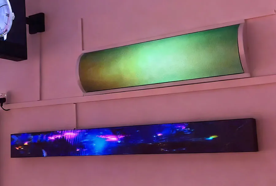
TW VISION Bendable Screen Technology For Custom Curved Displays
TW VISION’s bendable screen technology represents a practical and scalable approach to creating custom curved displays for a wide range of industries — automotive, digital signage, architecture, gaming, and specialty consumer devices. Unlike conventional rigid glass screens or simple edge-curved panels, bendable displays enable continuous curvature, variable radii, and new form factors that can be designed to fit complex surfaces. This article explores the technical foundations, manufacturing methods, design considerations, application scenarios, advantages and trade-offs of TW VISION’s bendable display approach, and provides a compact analysis table to help product teams make informed integration decisions.
Fundamentals of Bendable Screen Technology
At the core of bendable screen technology are three interdependent layers: the flexible substrate and backplane, the emissive or transmissive optical stack, and the environmental encapsulation. TW VISION leverages advanced thin-film transistor (TFT) backplanes built on flexible polyimide or metal-foil substrates together with thin-film encapsulation (TFE) to protect the active layers from moisture and oxygen. Key technical points include:
– Flexible backplane: Oxide TFTs (IGZO) or low-temperature polycrystalline silicon (LTPS) fabricated on a polyimide substrate allow good electron mobility and pixel drive control while tolerating mechanical bend cycles.
– Emissive layer: For high contrast and deep blacks, OLED materials are commonly used. Emerging microLED implementations can deliver higher brightness and longer lifetimes and are also compatible with flexible substrates in select processes.
– Neutral mechanical plane and strain management: To minimize device stress during curvature, the active electronics are positioned at or near the neutral mechanical plane. Layer thickness optimization, material modulus selection, and controlled adhesive layers reduce strain on brittle components.
– Thin-film encapsulation (TFE): Multi-layer inorganic/organic barrier stacks deposited by atomic layer deposition (ALD) or plasma-enhanced chemical vapor deposition (PECVD) protect the emissive layer. TFE replaces bulk glass encapsulation to retain flexibility and environmental resistance.
– Flexible interconnects and drivers: Bendable displays require flexible printed circuits (FPCs), anisotropic conductive films (ACF), or low-profile flex cables with strain relief. Intelligent placement of driver ICs in flexible “islands” or use of chip-on-flex reduce stress during bending.
Manufacturing Approaches and Yield Considerations
Manufacturing bendable displays involves specialized tooling and process control to deliver acceptable yields:
– Roll-to-roll (R2R) vs. batch processing: R2R deposition enables continuous processing of flexible substrates and is cost-effective for high-volume runs. Batch vacuum deposition and photolithography are used for higher-resolution TFT arrays and precise patterning.
– Laser annealing and low-temperature processes: Thermal budgets are constrained by polymer substrates; laser or photonic annealing can locally crystallize silicon layers without heating the entire substrate.
– Layer alignment and strain testing: Continuous monitoring of substrate flatness and layer alignment is vital. Automated optical inspection (AOI) and mechanical fatigue testing (bending cycles across radii) detect early failures.
– Yield drivers: Defect density in emissive material, particle contamination during deposition, and micro-cracking in brittle layers are principal yield detractors. TW VISION mitigates these with cleanroom upgrades, improved barrier films, and stress-engineered layer stacks.
Design Considerations for Custom Curved Displays
Designing with TW VISION bendable screens requires collaboration between industrial design, mechanical engineering, and electronics teams. Key considerations:
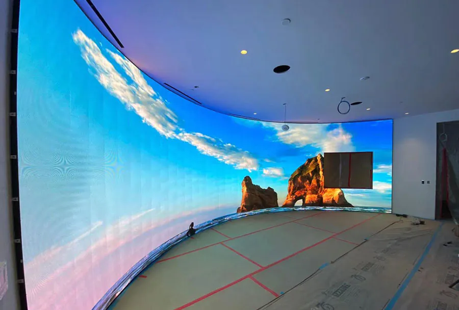
– Curvature specification: Define minimum bend radius, axis of curvature (cylindrical vs. compound), and whether curvature is fixed or variable across the panel.
– Pixel density and resolution: Higher pixel densities demand more precise TFT patterning and tighter process control. Decide whether the display will be viewed at close range (requiring high PPI) or from distance.
– Optical uniformity: Curvature can introduce viewing-angle-dependent brightness and color shifts. Compensation methods include optical lamination, anti-glare coatings, and per-pixel calibration in the display controller.

– Thermal management: Emissive displays generate heat that can accelerate degradation. Thermal spreaders (thin copper or graphite layers), controlled duty cycles, and heat-conductive adhesives are effective solutions.
– Mounting and sealing: The mechanical mounting must avoid concentrated stress points. Use distributed clamps, flexible adhesives, and allow for thermal expansion. Ensure environmental seals maintain TFE integrity at the edges.
Performance Metrics and Reliability
When evaluating bendable displays, typical performance metrics include bending radius, cycle life, luminance, color gamut, response time, and environmental ratings (IP). Practical targets for commercial use:
– Typical bend radius: Many applications support radii down to 4–10 mm for small panels; larger public signage or automotive installations commonly use radii of 100 mm and above.
– Repeatability: Commercial-grade bendable displays should survive tens of thousands of bending cycles in stress zones and millions in low-strain zones.
– Lifetime: OLED flexible designs may have shorter lifetimes than rigid alternatives due to permeation risks; advanced TFE and optimized pixel drive can extend operational life into the tens of thousands of hours at moderate brightness.
– Thermal and humidity resistance: Successful designs meet automotive-grade temperature ranges (-40°C to +85°C) and humidity cycling when appropriate encapsulation and sealing are used.
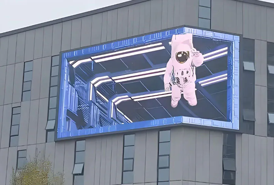
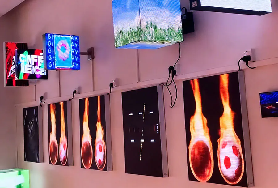
Applications Enabled by TW VISION Bendable Displays
TW VISION’s technology unlocks a range of high-value applications:
– Automotive interiors: Continuous curved instrument clusters, wrap-around infotainment screens, and passenger entertainment panels with seamless curves that follow dash contours.
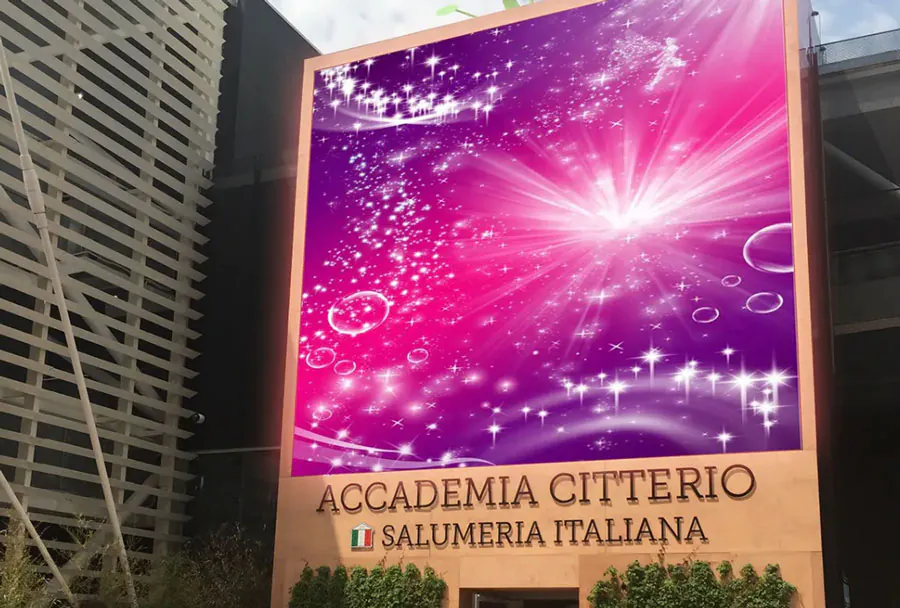
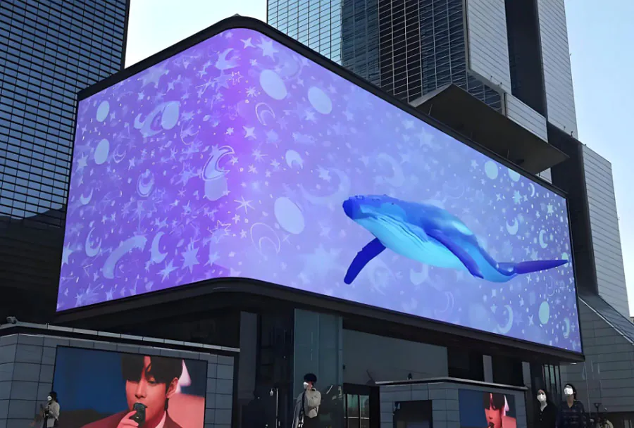
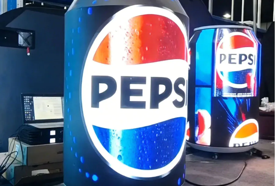
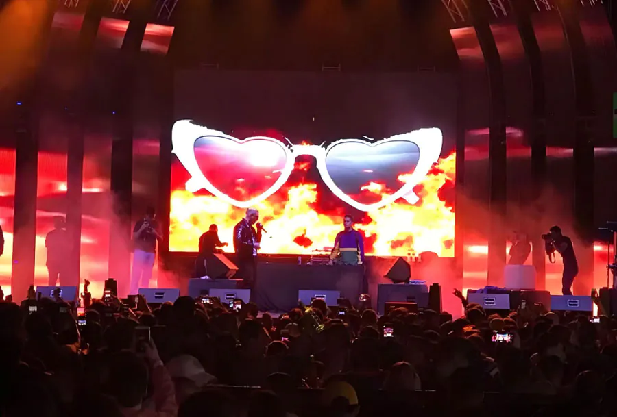
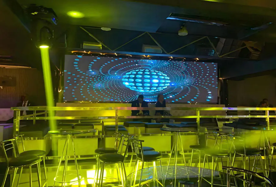
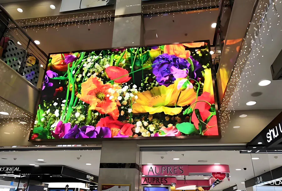
– Digital signage and architectural installations: Sculptural displays that conform to columns, ceilings, and bespoke retail installations for immersive branding.
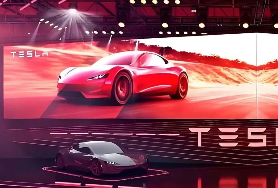
– Gaming and simulation: Ultra-wide curved monitors and cockpit displays with controlled curvature for improved immersion and peripheral visibility.
– Wearables and specialty devices: Curved instrument panels, helmet HUDs, and medical devices where conformal fit improves ergonomics.
– Transportation and public spaces: Curved information displays in trains, buses, and airports designed to maximize visibility and aesthetics.
Comparative Analysis Table
Below is a focused analysis table that helps compare practical parameters when selecting or specifying a TW VISION bendable display for a custom curved application.
| Parameter | Typical Range / Value | TW VISION Implementation | Primary Benefit | Design Recommendation |
|---|---|---|---|---|
| Bend Radius | 4 mm – 1000 mm | Custom-specified radii; supports continuous curvature | Enables tight-fit and large-area curves | Specify min radius early; avoid abrupt curvature transitions |
| Substrate Thickness | 30 μm – 200 μm | Polyimide 50–125 μm typical | Balance of flexibility and mechanical robustness | Use thicker substrate for high-stress mounting areas |
| Encapsulation WVTR | 10^-4 – 10^-6 g/m2/day | Multi-layer ALD/organic TFE achieving ~10^-5 g/m2/day | Extends OLED lifetime, reduces failures | Target ≤10^-5 for outdoor/automotive use |
| Operating Brightness | 300 – 2000 nits | Optimized OLED or microLED stacks to 1000+ nits | Improves legibility in ambient light | Higher brightness needs greater thermal design |
| Cycle Life (bend cycles) | 10^3 – 10^6 | 100k targeted for commercial panels | Ensures durability for repeated handling | Test prototype across intended bend profiles |
Integration and System-Level Considerations
Integrating a bendable display into a product requires system-level thinking:
– Electronics placement and shielding: Driver ICs should be placed in low-strain areas or on flex “islands” with strain-relief features. EMI shielding must be flexible and maintain performance under bend.
– Connectors and harness routing: Use reinforced terminations, strain relief, and routing channels that avoid sharp bends that exceed the screen’s curvature specification.

– Software calibration: Curved geometry may require geometric correction and color calibration to compensate for optical effects. TW VISION often supplies LUTs (lookup tables) and calibration routines tailored to each curvature profile.
– Safety and regulatory: Automotive and public-safety applications require compliance with relevant certifications (e.g., ISO, FMVSS, UL). Environmental testing (thermal/HAST) should be part of the qualification plan.
Limitations, Failure Modes, and Mitigation Strategies
Bendable displays introduce failure modes that must be addressed:
– Moisture ingress: Even small defects in TFE can allow moisture that degrades emissive materials. Mitigate with redundant barrier layers and edge sealing.
– Mechanical fatigue: Repeated flexing at stress concentration points can induce micro-cracks. Mitigate via neutral plane design, flexible adhesives, and rounded mounting features.
– Delamination and peel: Poor adhesion between layers or to mounting frames can cause delamination under thermal cycling. Use compatible adhesives and surface treatments.
– Optical non-uniformity: Curvature can change viewing angles and perceived brightness. Optical films and per-channel calibration reduce visible artifacts.
Cost and Supply Chain Considerations
Bendable display costs remain higher than commodity rigid panels due to specialized materials and lower initial yields. Key cost drivers include:
– Substrate and barrier materials (high-performance polyimide and ALD films are more expensive).
– Facility and tooling upgrades for R2R or flexible handling.
– Lower initial yields, which improve with volume and process maturity.
– Custom mechanical enclosures and adhesives for mounting and sealing.
TW VISION’s approach emphasizes modularity to lower integration costs: standardized drive electronics that can be adapted to various curvature profiles, and design-for-manufacturing guidance to reduce iteration cycles.
Future Directions and Emerging Opportunities
Several trends will expand capability and reduce cost:
– Flexible microLED: Combining microLED brightness and lifetime with flexible substrates could overcome OLED longevity limits for high-brightness applications.
– Improved barrier technologies: New ALD and hybrid barrier films with lower WVTR and higher mechanical flexibility will improve lifetimes and reliability.
– Advanced R2R manufacturing: More automated roll-to-roll lines that integrate patterning, encapsulation, and QC will drive volume and cost improvements.
– Active curvature displays: Future systems may incorporate variable curvature via mechanical actuation, enabling dynamic reconfiguration of display geometry for adaptive UX.
– Integration with sensors: Bendable displays could integrate touch, proximity, and biometric sensors in a conformal surface.
Practical Recommendations for Product Teams
– Define curvature and environmental specs at project outset. Curvature is best treated as a primary mechanical requirement rather than a cosmetic one.
– Prototype early with TW VISION engineering support. Iterative samples help reveal stress points and integration challenges.
– Plan for calibration: software-level compensation for color and geometric distortions will improve perceived quality.
– Test for the intended use environment: include thermal cycling, humidity exposure, vibration, and mechanical fatigue tests in the qualification plan.
– Balance performance targets: higher brightness and smaller pixel pitch may increase thermal and yield challenges; choose the right trade-offs for your use case.
TW VISION’s bendable screen technology provides a practical path to producing custom curved displays that expand design freedom and enable new use cases across industries. The combination of flexible backplanes, advanced thin-film encapsulation, and strain-aware mechanical design enables continuous curvature, strong optical performance, and reliable operation when properly engineered. Successful adoption requires careful early collaboration between design, mechanical, and electronics teams, a rigorous testing and validation program, and realistic trade-off decisions between brightness, lifetime, cost, and mechanical robustness. As barrier technologies, flexible microelectronics, and roll-to-roll manufacturing continue to improve, bendable displays will become increasingly accessible, unlocking fresh opportunities in automotive UX, architectural signage, immersive gaming, and beyond.